Troubleshooting & Repair Model 200E Instruction Manual
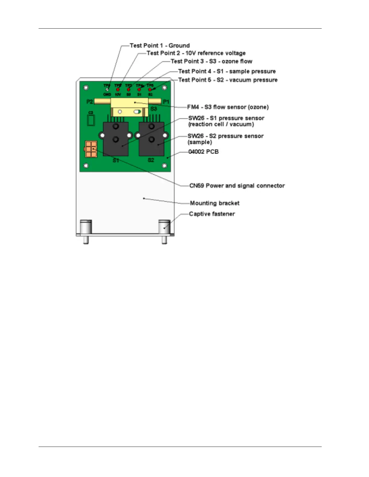
Figure 11-5: Pressure / Flow Sensor Assembly
11.5.15.3. Ozone Flow
Measure the voltage across TP1 and TP3. With proper ozone flow (80 cm³/min at the ozone
dryer inlet), this should be approximately 2.0 ± 0.2 V (this voltage will vary with altitude).
With flow stopped (pump turned off), the voltage should be approximately 0 V. If the
voltage is incorrect, the flow sensor or the board may be faulty. A cross-leak to vacuum
inside the Perma Pure dryer may also cause this flow to increase significantly, and the
voltage will increase accordingly. Also, make sure that the gas flows from P1 to P2 as
labeled on the flow sensor (“high” pressure P1 to “low” pressure P2 or “Port” 1 to “Port” 2).
11.5.16. NO
2
Converter
The NO
2
converter assembly can fail in two ways, an electrical failure of the band heater
and/or the thermocouple control circuit and a performance failure of the converter itself.
1) NO
2
converter heater failures can be divided into two possible problems:
• Temperature is reported properly but heater does not heat to full temperature. In
this case, the heater is either disconnected or broken or the power relay is broken.
214 044100102 Rev A