Model 200E Instruction Manual Operating Instructions
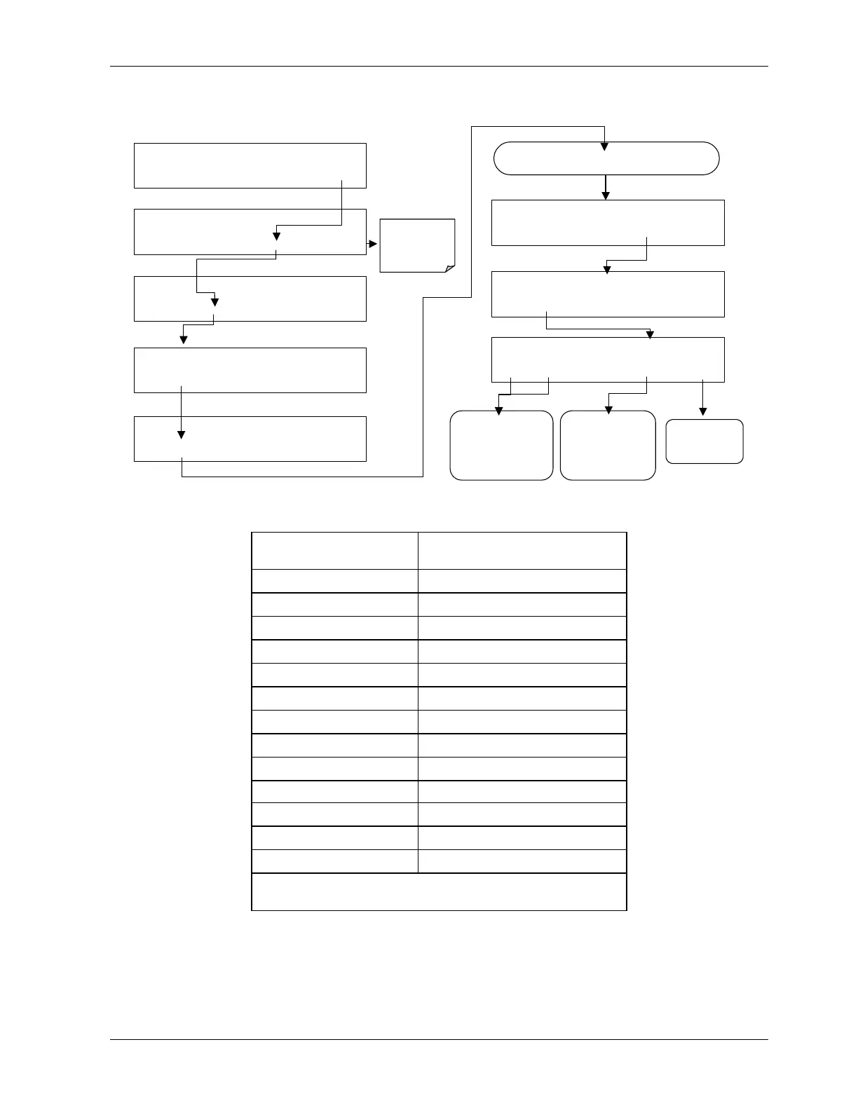
To activate the A4 channel and select a test function, follow this key sequence:
SAMPLE RANGE = 500.0 PPB NOX=X.X
< TST TST > CAL SETUP
SETUP X.X
PRIMARY SETUP MENU
CFG DAS RNGE PASS CLK MORE EXIT
SETUP X.X
SECONDARY SETUP MENU
COMM VARS DIAG EXIT
DIAG SIGNAL I / O
NEXT ENTR EXIT
DIAG ANALOG OUTPUT
PREV NEXT ENTR EXIT
DIAG TCHN TEST CHANNEL: NONE
NEXT ENTR EXIT
DIAG TEST CHAN OUTPUT
PREV NEXT ENTR EXIT
EXIT returns
to the main
SAMPLE
display
Continue to press NEXT until …
DIAG TCHN TEST CHANNEL: PMT DETECTOR
PREV NEXT ENTR EXIT
Press PRE
or NEXT
to move through the
list of available
parameters
(Table 6-9)
Press EXIT to
return to the
DIAG
menu
Press ENTR to
select the displayed
parameter and to
activate the test
channel.
Table 6-13: Test Parameters Available for Analog Output A4
Test Channel Test parameter range
1
NONE Test channel is turned off
PMT DETECTOR 0-5000 mV
Ozone flow 0-1000 cm³/min
sample flow 0-1000 cm³/min
SAMPLE PRESSure 0-40 in-Hg-A
rcell pressure 0-40 in-Hg-A
rcell temp 0-70° C
manifold temp 0-70° C
izs temp 0-70° C
conv temp 0-500° C
pmt temp 0-50° C
CHASSIS TEMP 0-70° C
HVPS VOLTAGE 0-5000 V
1
This refers to the voltage range of the parameter and
not the output signal of the test channel.
Once a TEST function is selected, the instrument begins to report a signal on the A4 output
and adds TEST= to the list of test functions viewable on the display (just before the TIME
display).
044100102 Rev A 69