Getting Started Model 200E Instruction Manual
Table 3-2: Analog Output Pin-Outs
Pin Analog Output Data Type Voltage Signal Current Signal
1 V Out I Out +
2
A1 NO
X
Ground I Out -
3 V Out I Out +
4
A2 NO
Ground I Out -
5 V Out I Out +
6
A3 NO
2
Ground I Out -
7 V Out not available
8
A4 Test Channel
Ground not available
If you wish to utilize the analyzer’s status outputs to interface with a device that accepts
logic-level digital inputs, such as programmable logic controller (PLC) chips, you can access
them through a 12 pin connector on the analyzer’s rear panel labeled STATUS.
EMITTER BUS
FOR PINS 1-8
STATUS
1 2 3 4 5 6 7 8 D
+
SYSTEM O
HIGH RANGE
CONC VALID
ZERO CAL
SPAN CAL
DIAGNOSTIC
MODE
LOW SPAN
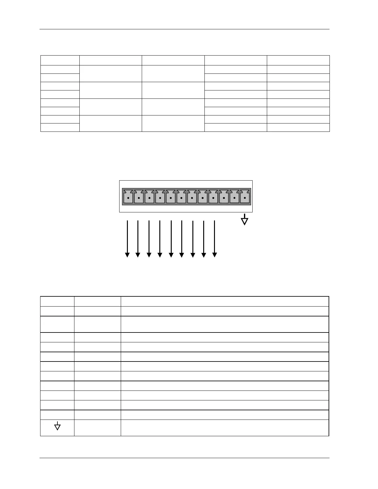
Figure 3-8: Status Output Connector
Table 3-3: Status Output Signals
Pin # Status Condition (ON = Conducting)
1 SYSTEM OK ON if no faults are present.
2 CONC VALID ON if concentration measurement (NO, NO2 or NOx) is valid.
OFF any time the hold-off feature is active.
3 HIGH RANGE ON if unit is in high range of the Auto Range Mode.
4 ZERO CAL ON whenever the instrument is in ZERO point calibration mode.
5 SPAN CAL ON whenever the instrument is in SPAN point calibration mode.
6 DIAG MODE ON whenever the instrument is in diagnostic mode.
7 Unused
8 Unused
D EMITTER BUS The emitters of the transistors on pins 1-8 are tied together.
Unused
+ DC POWER + 5 VDC, 300 mA (combined rating with Control Output, if used).
Digital
Ground
The ground level from the analyzer’s internal DC power supplies
18 044100102 Rev A