Model 200E Instruction Manual Operating Instructions
6. OPERATING INSTRUCTIONS
To assist in navigating the analyzer’s software, a series of menu trees can be found in
Appendix A of this manual along with an index of software commands and references to the
respective manual sections.
NOTE
The flow charts appearing in this section contain typical representations of the
analyzer’s display during the various operations being described. These
representations may differ slightly from the actual display of your instrument.
6.1. Overview of Operating Modes
The M200E software has a variety of operating modes. Most commonly, the analyzer will be
operating in SAMPLE mode, in which sample gases are measured and a continuous read-
out of the gas concentration is displayed. Test and warning functions can be examined and
data can be viewed or downloaded.
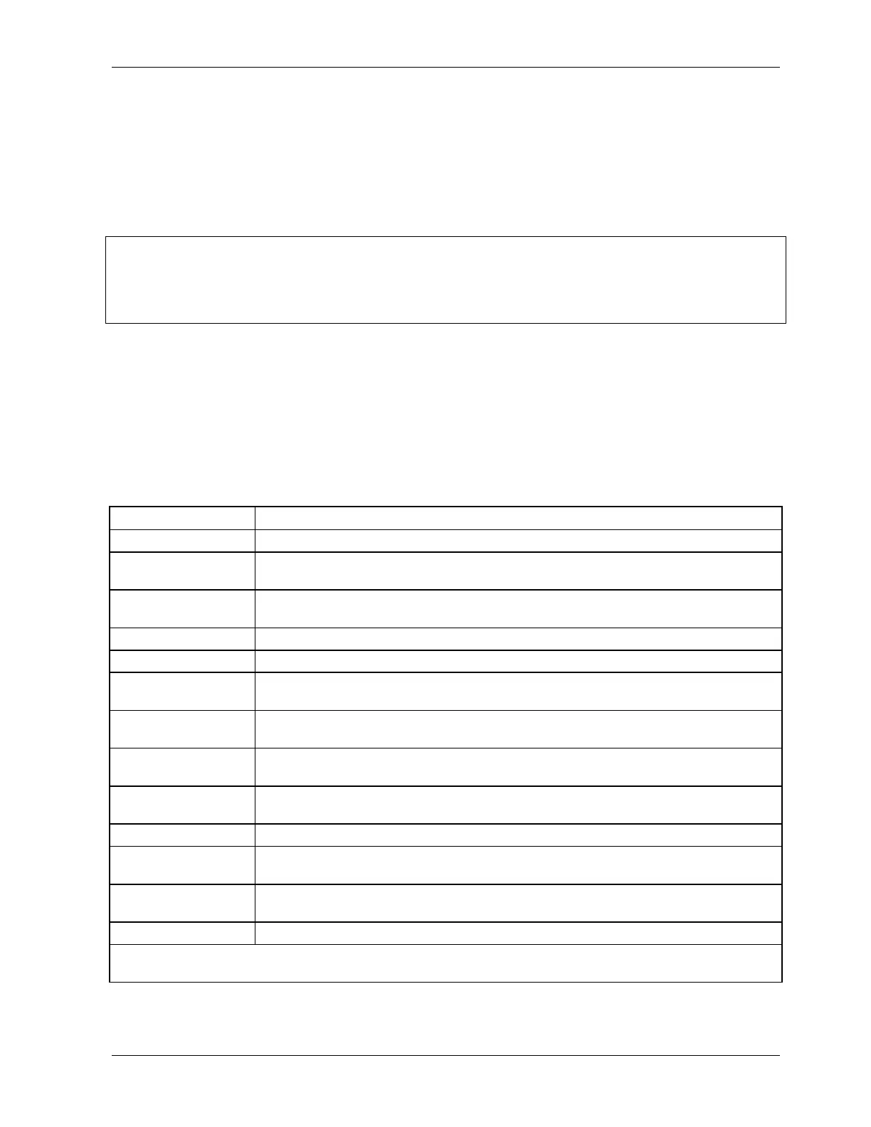
Table 6-1: Analyzer Operating modes
Mode Explanation
SAMPLE Sampling normally, flashing text indicates adaptive filter is on.
M-P CAL This is the basic calibration mode of the instrument and is activated by
pressing the CAL key.
SETUP X.#
2
SETUP mode is being used to configure the analyzer. The gas measurement
will continue during this process.
SAMPLE A Indicates that unit is in SAMPLE mode and AUTOCAL feature is activated.
ZERO CAL M
1
Unit is performing ZERO calibration procedure initiated manually by the user.
ZERO CAL A
1
Unit is performing ZERO calibration procedure initiated automatically by the
AUTOCAL feature.
ZERO CAL R
1
Unit is performing ZERO calibration procedure initiated remotely through the
COM ports or digital control inputs.
LO CAL A Unit is performing LOW SPAN (midpoint) calibration initiated automatically by
the analyzer’s AUTOCAL feature.
LO CAL R Unit is performing LOW SPAN (midpoint) calibration initiated remotely through
the COM ports or digital control inputs.
SPAN CAL M
1
Unit is performing SPAN calibration initiated manually by the user.
SPAN CAL A
1
Unit is performing SPAN calibration initiated automatically by the analyzer’s
AUTOCAL feature.
SPAN CAL R
1
Unit is performing SPAN calibration initiated remotely through the COM ports
or digital control inputs.
DIAG One of the analyzer’s diagnostic modes is active (Section 6.8).
1
Only Appears on units with Z/S valve or IZS options.
2
The revision of the analyzer firmware is displayed following the word SETUP, e.g., SETUP C.4.
044100102 Rev A 41