Model 200E Instruction Manual Operating Instructions
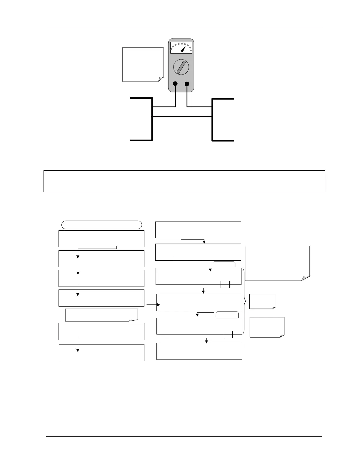
mA
IN OUT
V OUT +
V OUT -
I IN +
I IN -
Recording
Device
Anal
zer
See Table 3-2 for
pin assignments o
the Analog Out
connector on the
rear panel.
Figure 6-3: Setup for Calibrating Current Outputs
CAUTION
Do not exceed 60 V between current loop outputs and instrument ground.
To adjust the zero and span values of the current outputs, press SETUP-MORE-DIAG-ENTR-
NEXT-NEXT and then:
EXAMPLE
DIAG
ANALOG I / O CONFIGURATION
PREV NEXT ENTR EXIT
DIAG AIO AIN A/C FREQUENCY:
60 HZ
SET>
EDIT
EXIT
DIAG AIO AOUT CALIBRATED: NO
< SET SET> CAL EXIT
FROM ANALOG I/O CONFIGURATION MENU
DIAG AIO
CONC_OUT_2 RANGE: CURR
<SET SET> EDIT EXIT
DIAG AIO
CONC_OUT_2 CALIBRATED: NO
< SET CAL EXIT
DIAG AIO CONC_OUT_2 ZERO: 0 m
U100
UP10
UP DOWN DN10 D100 ENTR EXIT
DIAG AIO
CONC_OUT_CURR, NO CAL
< SET SET> EDIT EXIT
Press SET> to select the analog output channel
to be configured:. Then press EDIT to continue
DIAG AIO AIN CALIBRATED:
NO
SET>
EDIT
EXIT
ENTR returns
to the previous
menu.
Increase or decrease the current
output by 100, 10 or 1 counts. The
resulting change in output voltage is
displayed in the upper line.
Continue adjustments until the correct
current is measured with the current
meter.
DIAG AIO CONC_OUT_2 ZERO: 27 mV
U100 UP10
UP DOWN DN10 D100
ENTR EXIT
EXIT ignores the
new setting, ENTR
accepts the new
setting.
DIAG AIO CONC_OUT_2 CALIBRATED: YES
< SET
CAL
EXIT
DIAG AIO CONC_OUT_2 SPAN: 10000 m
U100 UP10
UP DOWN DN10
D100
ENTR EXIT
EXAMPLE
DIAG AIO CONC_OUT_2 ZERO: 9731 mV
U100 UP10 UP DOWN DN10 D100 ENTR EXIT
If a current meter is not available, an alternative method for calibrating the current loop
outputs is to connect a 250 Ω ±1% resistor across the current loop output. Using a
voltmeter, connected across the resistor, follow the procedure above but adjust the output
to the following values:
044100102 Rev A 67