Troubleshooting & Repair Model 200E Instruction Manual
• With the instrument running, set the instrument reporting range to SNGL (Section
6.5.3).
• Perform a full zero calibration using zero air (Section 7.2, 7.4, or7.5).
• Locate the preamplifier board (Figure 3-2).
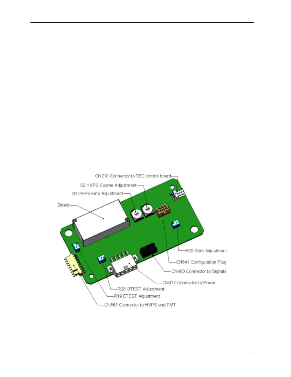
• Locate the following components on the preamplifier board (Figure 11-6):
• HVPS coarse adjustment switch (Range 0-9, then A-F).
• HVPS fine adjustment switch (Range 0-9, then A-F).
• Gain adjustment potentiometer (Full scale is 10 turns).
• Turn the gain adjustment potentiometer 12 turns clockwise to its maximum setting.
• While feeding 400 ppb NO (or 80% range value) to the analyzer and waiting until
the STABIL value is below 0.5 ppb, look at the front panel and scroll to the
NORM PMT value. This value should always be two times the span gas
concentration in ppb. With 400 ppb NO, the NORM PMT should show 800 mV on a
properly calibrated analyzer.
• Set the HVPS coarse adjustment to its minimum setting (0). Set the HVPS fine
adjustment switch to its maximum setting (F).
• Set the HVPS coarse adjustment switch to the lowest setting that will give you just
above 800 mV NORM PMT signal (2x span gas ppb value). The coarse adjustment
typically increments the NORM PMT signal in 100-300 mV steps.
Figure 1 -6: Pre-Amplifier Board Layout 1
• Adjust the HVPS fine adjustment such that the NORM PMT value is 800-830 mV.
The fine adjustment typically increments the NORM PMT value by about 30 mV. It
220 044100102 Rev A