Do you have a question about the Teledyne ULTRAFLOW 150 and is the answer not in the manual?
Explains symbols and associated cautions for Teledyne Monitor Labs equipment.
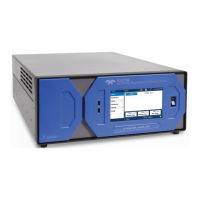
Describes the standard components of the Ultraflow 150 system.
Describes the modular, menu-driven panel with keypad, LCD, and network capabilities.
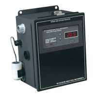
Explains the operator interface at the TIE for evaluation and setup from the stack.
Allows input of external pressure and temperature for converting flow volume to standard conditions.
Explains how transit times of ultrasonic tone bursts determine flow velocity, temperature, and volume.
Describes the enclosure's construction, material, and mounting of internal electronics.
Details the power supply, internal boards, and communication interfaces within the TIE.
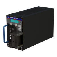
Details the modular design, enclosure dimensions, and internal components of the panel.
Explains power requirements, circuit overview, display, keypad, LEDs, and security switch.
Explains how to navigate menus, change parameters, and access protected screens.
Discusses software configuration for analog outputs, digital inputs, and digital outputs.
Outlines key factors for successful instrument operation and installation planning.
Emphasizes the importance of selecting an appropriate site for monitor accuracy and reliability.
Covers flange, mounting tube installation, and alignment procedures.
Focuses on configuring TIE variables to accurately represent physical site dimensions for calibration.
Details calibration via program variables and analog adjustments on the Enhanced Remote Panel.
Provides recommended schedules for inspections and maintenance activities.
Guides users through diagnosing and resolving system problems using status codes and service data.
Step-by-step guide for completing maintenance check sheets for the Ultraflow 150.
Provides categorized lists of parts for different maintenance levels.
Details the serial port capabilities and data formats for communication.
Lists variables specific to TIE 1, including date, time, velocities, and system parameters.
Lists variables specific to TIE 2, mirroring TIE 1's structure.
| Power Supply | 24 VDC or 110/230 VAC |
|---|---|
| Output Signal | 4-20mA, pulse, relay |
| Pipe Size Range | DN15 ~ DN6000 mm |
| Outputs | 4-20 mA, pulse, relay |
| Communication | Modbus |
| Enclosure | IP67 |