Model 200E Instruction Manual Getting Started
If you wish to use the analyzer to remotely activate the zero and span calibration modes,
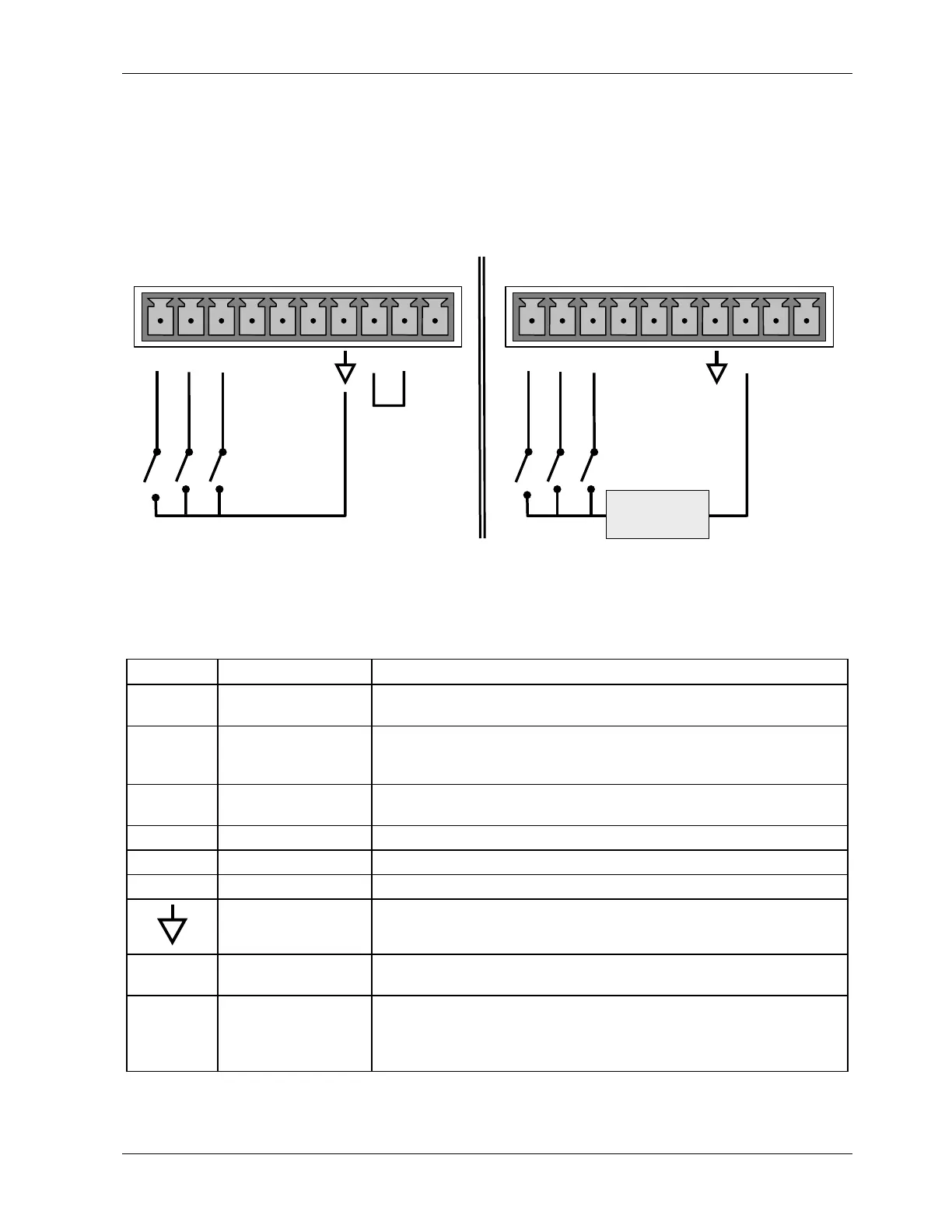
several digital control inputs are provided through a 10-pin connector labeled CONTROL IN
on the analyzer’s rear panel.
There are two methods for energizing the control inputs. The internal +5V available from
the pin labeled “+” is the most convenient method. However, if full isolation is required, an
external 5 VDC power supply should be used.
LOW SPAN
ZERO CAL
SPAN CAL
CONTROL IN
Local Power Connections
External Power Connections
LOW SPAN
ZERO CAL
SPAN CAL
CONTROL IN
-
+
5 VDC Power
Supply
A B C D E F U
+
A B C D E F U
+
Figure 3-9: Control Input Connector
Table 3-4: Control Input Signals
Input # Status Definition ON Condition
A
REMOTE ZERO CAL
The analyzer is placed in Zero Calibration mode. The mode field
of the display will read
ZERO CAL R.
B
REMOTE
LO SPAN CAL
The analyzer is placed in low span calibration mode as part of
performing a low span (midpoint) calibration. The mode field of
the display will read
LO CAL R.
C REMOTE
SPAN CAL
The analyzer is placed in Span Calibration mode. The mode field
of the display will read
SPAN CAL R.
D SPARE
E SPARE
F SPARE
Digital Ground
The ground level from the analyzer’s internal DC power supplies
(same as chassis ground).
U External Power
input
Input pin for +5 VDC required to activate pins A - F.
+ 5 VDC output Internally generated 5V DC power. To activate inputs A - F,
place a jumper between this pin and the “U” pin. The maximum
amperage through this port is 300 mA (combined with the
analog output supply, if used).
If you wish to utilize one of the analyzer’s two serial ports, attach the serial cable that is
included with the analyzer to the COM1 serial port on the rear panel. Connect the other end
044100102 Rev A 19