Model 200E Instruction Manual Operating Instructions
The following DC current output limits apply to the current loop modules:
Table 6-9: Analog Output Current Loop Range
Range Minimum Output Maximum Output
0-20 mA 0 mA 20 mA
These are the physical limits of the current loop modules, typical applications use 2-20 or 4-20
mA for the lower and upper limits. Please specify desired range when ordering this option. The
default offset for all ranges is 0 mA.
Pin assignments for the ANALOG output connector at the rear panel of the instrument:
Table 6-10: Analog Output Pin Assignments
Pin Analog
output
VOLTAGE
Signal
CURRENT
Signal
1 V Out I Out +
2
A1
Ground I Out -
3 V Out I Out +
4
A2
Ground I Out -
5 V Out I Out +
6
A3
Ground I Out -
7 V Out not available
8
A4
Ground not available
See Figure 6-1 for a visual representation and location of the analog output connector.
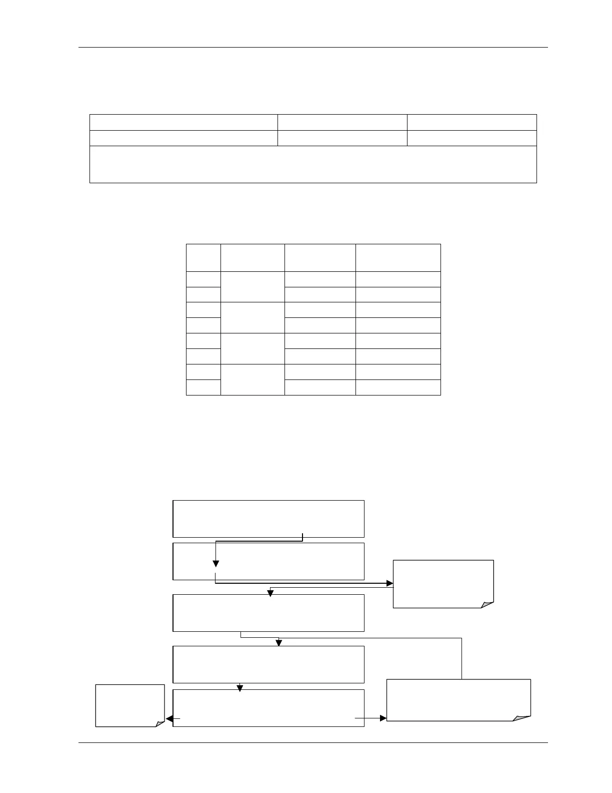
6.7.3.1. Analog Output Signal Type and Range Selection
To select an output signal type (DC Voltage or current) and level for one output channel
press SETUP - MORE - DIAG - ENTR - NEXT - NEXT and then:
DIAG
ANALOG I / O CONFIGURATION
PREV NEXT ENTR EXIT
DIAG AIO AOUTS CALIBRATED: NO
< SET
SET>
CAL
EXIT
DIAG AIO OUTPUT RANGE:
5V
0.1V 1V 5V 10V CURR ENTR EXIT
These keys set
the signal level
and type of the
selected channel
DIAG AIO
CONC_OUT_2:5V, CAL
< SET SET>
EDIT
EXIT
Press
SET>
to select the
analog output channel to be
configured. Press EDIT to
continue
DIAG AIO
CONC_OUT_2 RANGE: 5V
SET> EDIT EXIT
Pressing ENTR records the new setting
and returns to the previous menu.
Pressing EXIT ignores the new setting and
returns to the previous menu.
044100102 Rev A 61