Model 200E Instruction Manual Troubleshooting & Repair
The acceptable ranges for these test functions are listed in Appendix A-3. The actual values
for these test functions on checkout at the factory were also listed in the Final Test and
Validation Data Sheet, which was shipped with the instrument. Values outside the
acceptable ranges indicate a failure of one or more of the analyzer’s subsystems. Functions
with values that are within the acceptable range but have significantly changed from the
measurements recorded on the factory data sheet may also indicate a failure or a
maintenance item. A problem report worksheet has been provided in Appendix C (T-API
part number 04503) to assist in recording the value of these test functions. The following
table contains some of the more common causes for these values to be out of range.
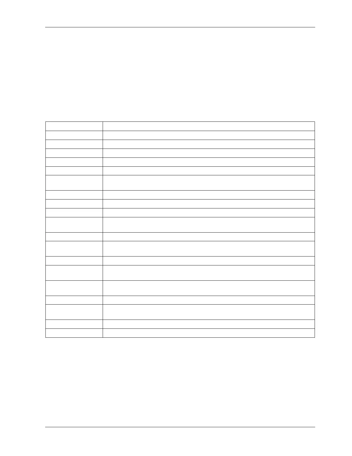
Table 11-1: Test Functions - Possible Causes for Out-Of-Range Values
Test Function Indicated Failure(s)
NOx STB Unstable concentrations; leaks
SAMPLE Fl Leaks; clogged critical flow orifice
OZONE FL Leaks; clogged critical flow orifice
PMT Calibration off; HVPS problem; no flow (leaks)
NORM PMT AutoZero too high
AZERO
Leaks; malfunctioning NONOx or AutoZero valve; O
3
air filter cartridge
exhausted
HVPS HVPS broken; calibration off; preamp board circuit problems
RCELL TEMP Malfunctioning heater; relay board communication (I
2
C bus); relay burnt out
BOX TEMP Environment out of temperature operating range; broken thermistor
PMT TEMP
TEC cooling circuit broken; relay board communication (I
2
C bus); 12 V power
supply
IZS TEMP (option) Malfunctioning heater; relay board communication (I
2
C bus); relay burnt out
MOLY TEMP
Malfunctioning heater; disconnected or broken thermocouple; relay board
communication (I
2
Z bus); relay burnt out; incorrect AC voltage configuration
RCEL (pressure) Leak; malfunctioning valve; malfunctioning pump; clogged flow orifices
SAMP (pressure)
Leak; malfunctioning valve; malfunctioning pump; clogged flow orifices;
sample inlet overpressure;
NOX SLOPE
HVPS out of range; low-level (hardware) calibration needs adjustment; span
gas concentration incorrect; leaks
NOX OFF Incorrect span gas concentration; low-level calibration off
NO SLOPE
HVPS out of range; low-level calibration off; span gas concentration incorrect;
leaks
NO OFFS Incorrect span gas concentration; low-level calibration off
Time of Day Internal clock drifting; move across time zones; daylight savings time?
11.1.3. Using the Diagnostic Signal I/O Function
The signal I/O parameters found under the diagnostics (DIAG) menu combined with a
thorough understanding of the instrument’s theory of operation (Chapter 10) are useful for
troubleshooting in three ways:
• The technician can view the raw, unprocessed signal level of the analyzer’s critical
inputs and outputs.
044100102 Rev A 191