Getting Started Model 200E Instruction Manual
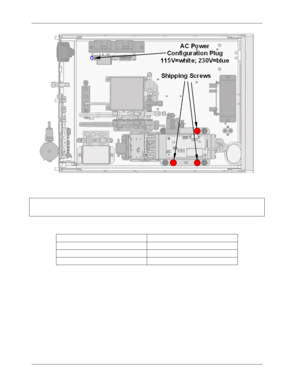
Figure 3-1: Location of Shipping Screws and Power Configuration Plug
NOTE
Save these shipping screws and re-install them whenever the unit is shipped.
A certain ventilation clearance is required for the operation of the analyzer:
Area Minimum required clearance
Back of the instrument 10 cm / 4 inches
Sides of the instrument 2.5 cm / 1 inch
Above and below the instrument 2.5 cm / 1 inch
Various rack mount kits are available for this analyzer. See Chapter 5 of this manual for
more information.
10 044100102 Rev A