Model 200E Instruction Manual Troubleshooting & Repair
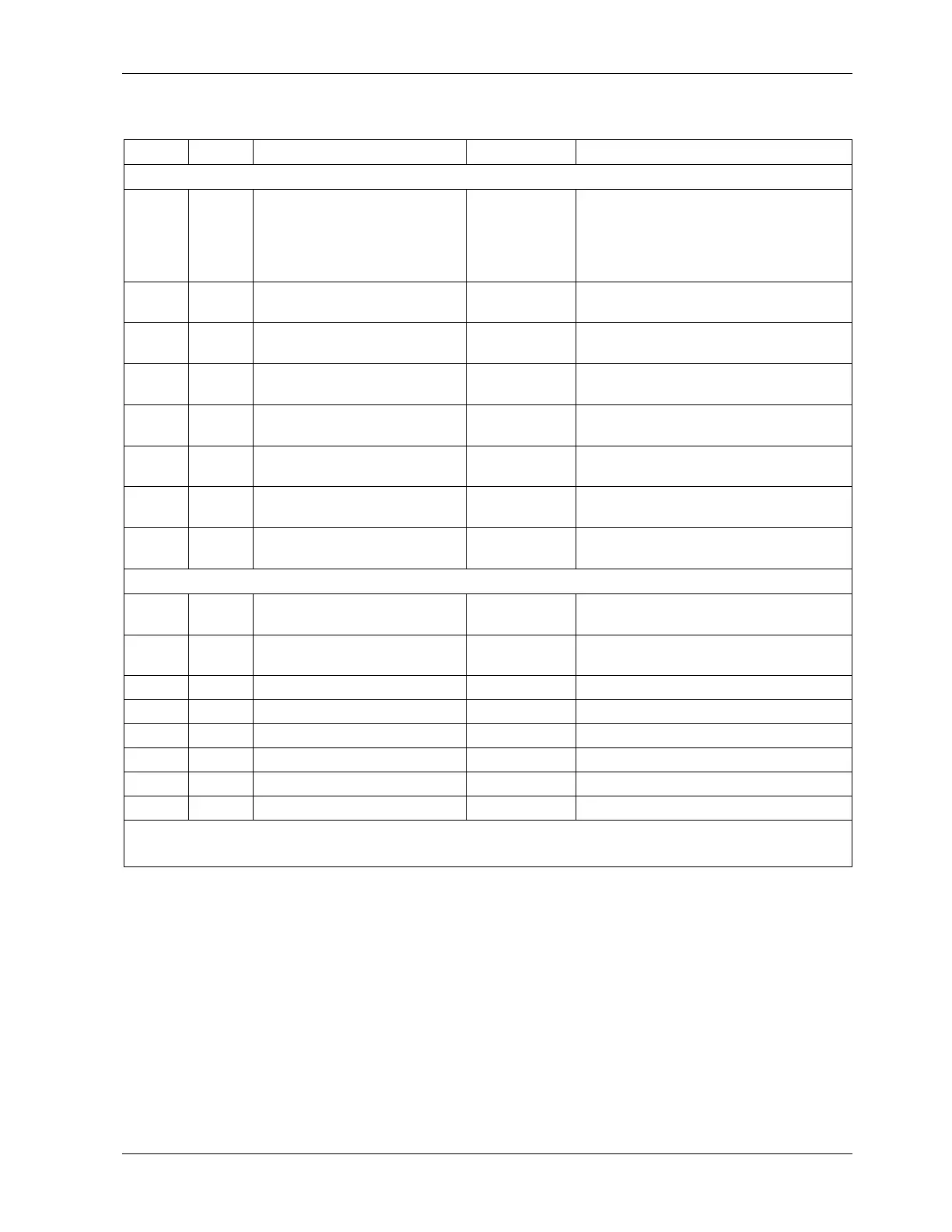
Table 11-2: Relay Board Status LEDs
LED Color Function Fault Status Indicated Failure(s)
LED Row 1 (center of board)
D1 red Watchdog Circuit; I
2
C bus
operation.
Continuously
ON or OFF
Failed or halted CPU; faulty
motherboard, keyboard, relay
board; wiring between mother-
board, keyboard or relay board; +5
V power supply
D2
yellow Relay 0 - reaction cell
heater
Continuously
ON or OFF
Heater broken, thermistor broken
D3 yellow Relay 1 - NO
2
converter
heater
Continuously
ON or OFF
Heater broken, thermocouple
broken
D4
1
yellow Relay 2 - manifold heater Continuously
ON or OFF
Heater broken, thermistor broken
D7
2
green Valve 0 - zero/span valve
status
Continuously
ON or OFF
Valve broken or stuck, valve driver
chip broken
D8
2
green Valve 1 - sample/cal valve
status
Continuously
ON or OFF
Valve broken or stuck, valve driver
chip broken
D9
green Valve 2 - auto-zero valve
status
Continuously
ON or OFF
Valve broken or stuck, valve driver
chip broken
D10 green Valve 3 - NO/NO
x
valve
status
Continuously
ON or OFF
Valve broken or stuck, valve driver
chip broken
LED Row 2 (top of board)
D5 yellow Relay 3 - IZS heater Continuously
ON or OFF
Heater broken, thermistor broken
D6 yellow Relay 4 – (O
2
sensor heater
200EH/EM)
N/A N/A
D11 green Valve 4 – Spare N/A N/A
D12 green Valve 5 – Spare N/A N/A
D13 green Valve 6 – Spare N/A N/A
D14 green Valve 7 – Spare N/A N/A
D15 green Mosfet1/DC driver-Unused N/A N/A
D16 green Mosfet2/DC driver -Unused N/A N/A
1
Special configurations only
2
Only active for instruments with Z/S valve or IZS options installed
11.2. Gas Flow Problems
The M200E has two main flow paths, the sample flow and the flow of the ozone supply air.
With IZS or zero/span valve option installed, there is a third (zero air) and a fourth (span
gas) flow path, but either one of those is only controlled by critical flow orifices and not
displayed on the front panel or stored to the iDAS. The full flow diagrams of the standard
configuration and with options installed (Appendix D, document 04574) help in trouble-
shooting flow problems. In general, flow problems can be divided into three categories:
• Flow is too high
• Flow is greater than zero, but is too low, and/or unstable
044100102 Rev A 195