Model 200E Instruction Manual Operating Instructions
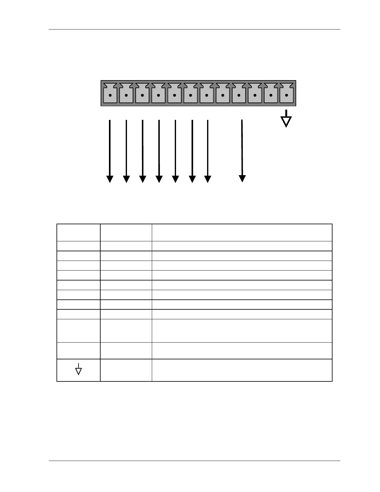
The status outputs are accessed through a 12 pin connector on the analyzer’s rear panel
labeled STATUS. The function of each pin is defined in Table 6-14.
COMMON
EMITTERS
STATUS
1 2 3 4 5 6 7 8 D
+
SYSTEM O
HIGH RANGE
CONC VALID
ZERO CAL
SPAN CAL
DIAGNOSTIC MODE
LOW SPAN
GROUND
Figure 6-4: Status Output Connector
Table 6-14: Status Output Pin Assignments
Connector
Pin
Status Condition (ON=conducting)
1 SYSTEM OK ON if no faults are present.
2 CONC VALID ON if concentration measurement is valid, OFF when invalid.
3 HIGH RANGE ON if unit is in high range of any AUTO range mode.
4 ZERO CAL ON whenever the instrument is in ZERO calibration mode.
5 SPAN CAL ON whenever the instrument is in SPAN calibration mode.
6 DIAG MODE ON whenever the instrument is in DIAGNOSTIC mode.
7 LOW RANGE ON if unit is in low range of any AUTO range mode.
8 Unused.
D EMITTER BUS
The emitters of the transistors on pins 1-8 are bussed
together. For most applications, this pin should be connected
to the circuit ground of the receiving device.
+ DC POWER
+ 5 VDC, 30 mA maximum (combined rating with Control
Inputs).
DIGITAL
GROUND
The ground from the analyzer’s internal, 5/±15 VDC power
supply.
6.8.2. Control Inputs
Control inputs allow the user to remotely initiate ZERO and SPAN calibration modes are
provided through a 10-pin connector labeled CONTROL IN on the analyzer’s rear panel.
These are opto-isolated, digital inputs that are activated when a 5 VDC signal from the “U”
pin is connected to the respective input pin.
044100102 Rev A 73