Operating Instructions Model 200E Instruction Manual
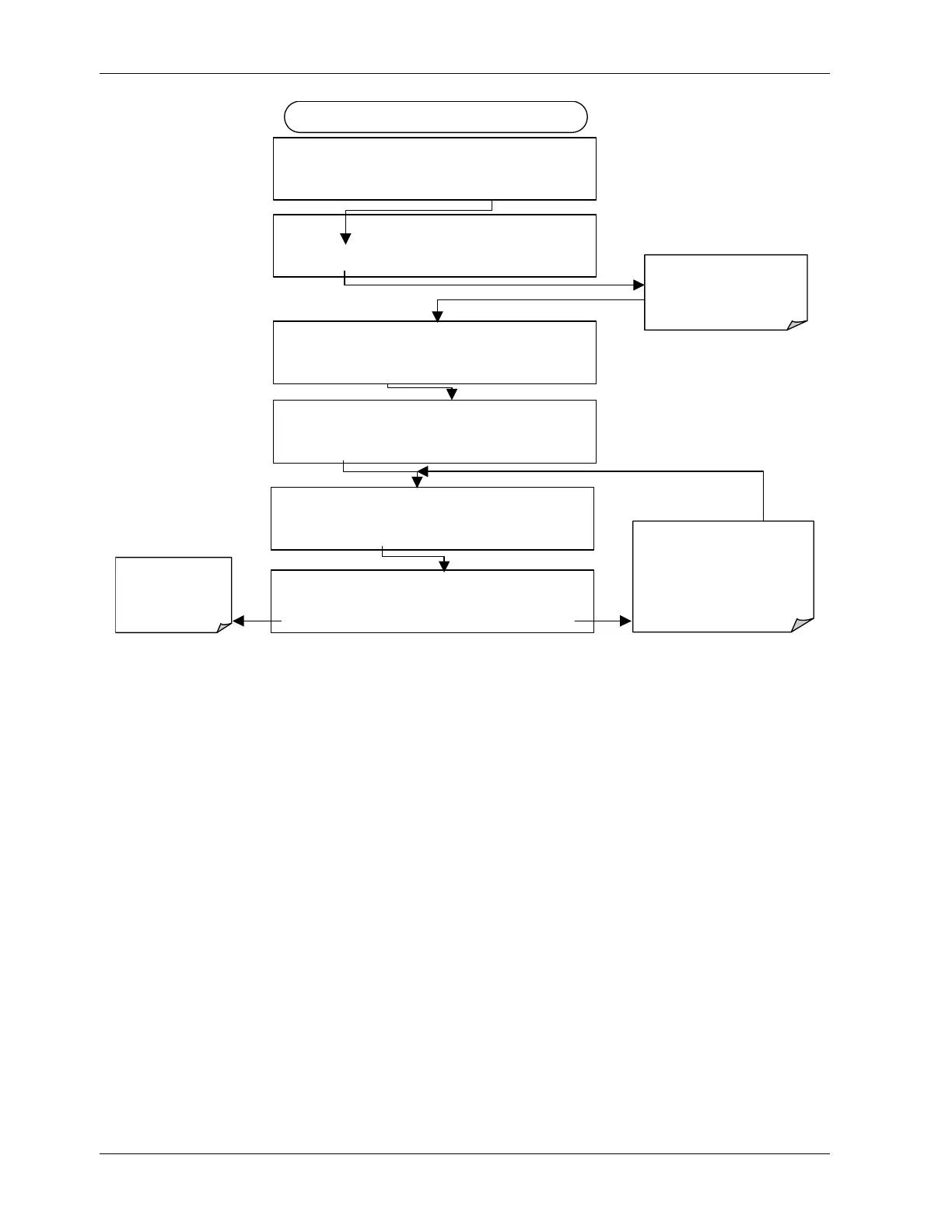
DIAG AIO RECORD OFFSET: 0 MV
+ 0 0 0 0 ENTR EXIT
DIAG
NALOG I / O CONFIGURATION
PREV NEXT ENTR EXIT
DIAG AIO AOUTS CALIBRATED: NO
< SET SET> CAL EXIT
FROM ANALOG I/O CONFIGURATION MENU
DIAG AIO CONC_OUT_2 RANGE: 5V
SET>
EDIT
EXIT
Set the recorder
offset (in mV) of
the selected
channel
DIAG AIO
CONC_OUT_2:5V, CAL
< SET SET>
EDIT
EXIT
DIAG AIO CONC_OUT_2 REC OFS: 0 mV
< SET SET>
EDIT
EXIT
Pressing ENTR accepts the
new setting and returns to the
previous menu.
Pressing EXIT ignores the new
setting and returns to the
previous menu.
Press SET> to select the
analog output channel to
be configured. Then press
EDIT to continue
6.7.3.5. Current Loop Output Adjustment
A current loop option is available and can be installed as a retrofit for each of the analog
outputs of the analyzer (Section 5.3). This option converts the DC voltage analog output to
a current signal with 0-20 mA output current. The outputs can be scaled to any set of limits
within that 0-20 mA range. However, most current loop applications call for either 2-20 mA
or 4-20 mA range. All current loop outputs have a +5% over-range. Ranges with the lower
limit set to more than 1 mA (e.g., 2-20 or 4-20 mA) also have a -5% under-range.
To switch an analog output from voltage to current loop, follow the instructions in
Section 6.7.1 and select CURR from the list of options on the “Output Range” menu.
Adjusting the signal zero and span values of the current loop output is done by raising or
lowering the voltage of the respective analog output. This proportionally raises or lowers
the current produced by the current loop option.
Similar to the voltage calibration, the software allows this current adjustment to be made in
100, 10 or 1 count increments. Since the exact current increment per voltage count varies
from output to output and from instrument to instrument, you will need to measure the
change in the current with a current meter placed in series with the output circuit
(Figure 6-4).
66 044100102 Rev A