Theory of Operation Model 200E Instruction Manual
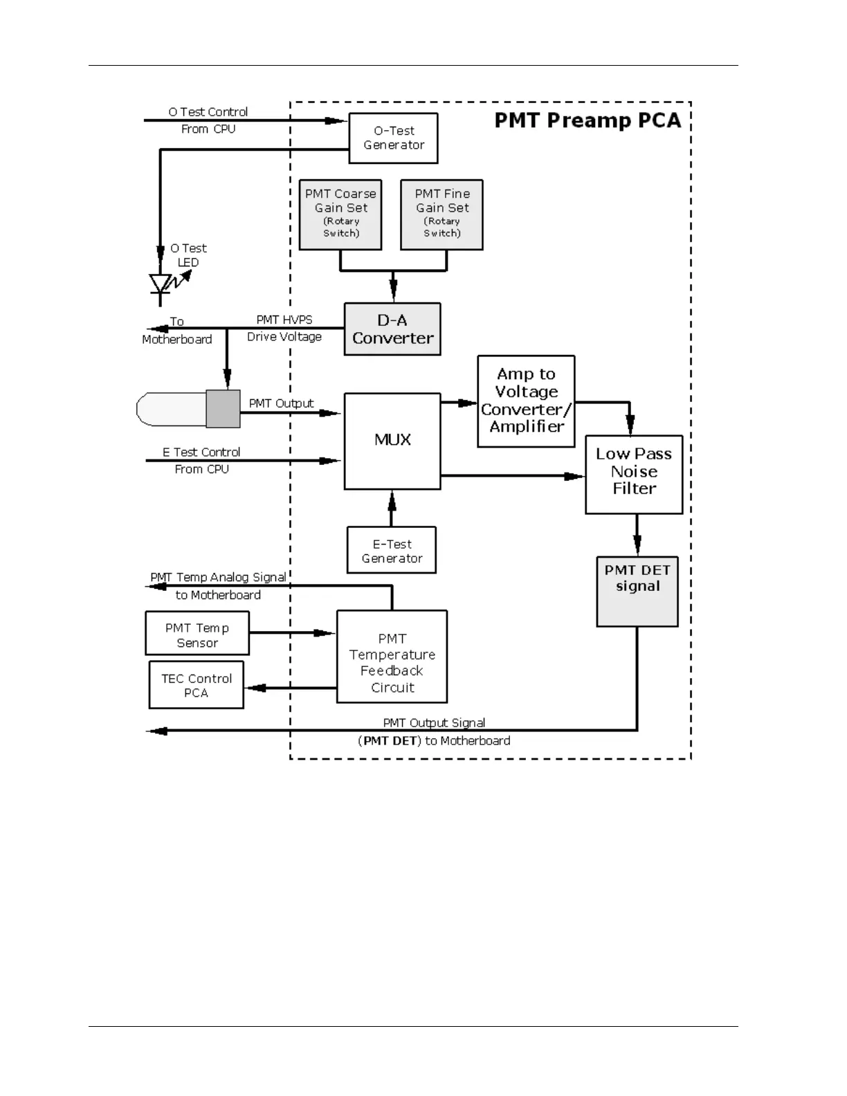
Figure 10-14: PMT Preamp Block Diagram
10.3.3. Pneumatic Sensor Board
The flow and pressure sensors of the M200E are located on a printed circuit assembly just
behind the PMT sensor. Refer to Section 11.5.15 for a figure and on how to test this
assembly. The signals of this board are supplied to the motherboard for further signal
processing. All sensors are linearized in the firmware and can be span calibrated from the
front panel.
176 044100102 Rev A