Troubleshooting & Repair Model 200E Instruction Manual
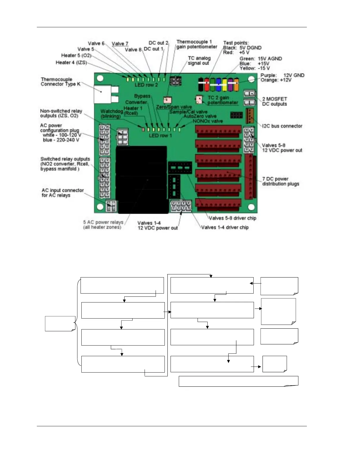
Figure 11-4: Relay Board PCA
To enter the signal I/O test mode to manually control I/O functions such as valves and
heaters, press the following keys while observing the relay board LEDs when toggling:
=
SAMPLE RANGE = 500.0 PPB NOX=X.X
< TST TST > CAL SETUP
EXAMPLE
SETUP X.X
PRIMARY SETUP MENU
CFG DAS RNGE PASS CLK MORE EXIT
SETUP X.X
SECONDARY SETUP MENU
COMM VARS DIAG EXIT
DIAG
SIGNAL I / O
PREV NEXT JUMP ENTR EXIT
DIAG I / O
Test Signals Displayed Here
PREV NEXT JUMP PRNT EXIT
Use the JUMP key to
go directly to a
specific signal
See Appendix A-4 for
a complete list of
available
SIGNALS
DIAG I / O
JUMP TO: 5
0 5 ENTR EXIT
Enter 05 to Jump
to Signal 5:
(CAL_LED)
DIAG I / O CAL_LED = ON
PREV NEXT JUMP ON PRNT EXIT
Exit to return
to the
DIAG menu
SETUP X.X ENTER DIAG PASS: 818
8 1 8
ENTR
EXIT
Use the
NEXT
&
PREV
keys to move between
signal types.
Pressing the PRNT key will send a formatted printout to the serial port and can be
ca
tured with a com
uter or other out
ut device.
EXIT returns
to the main
SAMPLE display
194 044100102 Rev A