Model 200E Instruction Manual Operating Instructions
Press SET> to select the analog output channel to be configured:
DISPLAYED AS = CHANNEL
CONC_OUT_1 = A1
CONC_OUT_2 = A2
CONC_OUT_3 = A3
TEST OUTPUT = A4
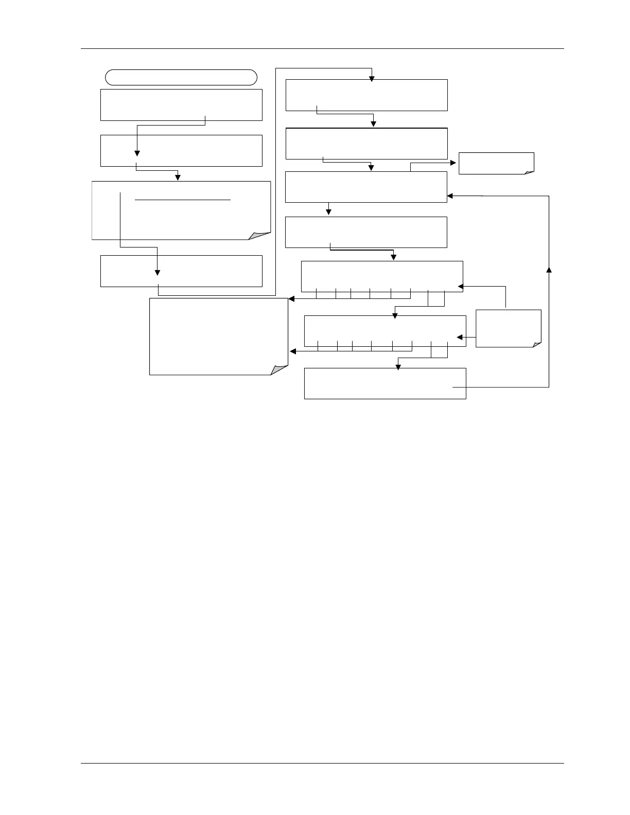
DIAG ANALOG I / O CONFIGURATION
PREV NEXT ENTR EXIT
DIAG AIO AOUTS CALIBRATED: NO
< SET SET> CAL EXIT
FROM ANALOG I/O CONFIGURATION MENU
DIAG AIO CONC_OUT_1 :5V, NO CAL
< SET SET> EDIT EXIT
DIAG AIO CONC_OUT_1 CALIBRATED: YES
< SET
CAL
EXIT
DIAG AIO CONC_OUT_1 RANGE: 5V
SET> EDIT EXIT
DIAG AIO CONC_OUT_2 CALIBRATED: NO
< SET CAL EXIT
DIAG AIO CONC_OUT_1 VOLT
Z : 0 m
U100 UP10 UP DOWN DN10 D100 ENTR EXIT
These keys increase / decrease the analog
output by 100, 10 or 1 counts. Continue
adjustments until the voltage measured at the
output of the analyzer and/or the input of the
recording device matches the value in the upper
right hand corner of the display to the tolerance
listed in Table 6-10.
The concentration display will not change. Only
the voltage reading of your voltmeter will change.
DIAG AIO CONC_OUT_1 VOLT
S : 4500 mV
U100 UP10 UP DOWN DN10 D100 ENTR EXIT
DIAG AIO CONC_OUT_1 REC OFS: 0 mV
< SET SET> EDIT EXIT
If AutoCal is ON, go to
Section 6.7.3
EXIT ignores the
new setting.
ENTR accepts the
new setting.
DIAG AIO CONC_OUT_1 AUTO CAL: OFF
< SET
SET>
EDIT
EXIT
6.7.3.4. Analog Output Offset Adjustment
Some analog signal recorders require that the zero signal is significantly different from the
baseline of the recorder in order to record slightly negative readings from noise around the
zero point. This can be achieved in the M200E by defining a zero offset, a small voltage
(e.g., 10% of span), which can be added to the signal of individual output channels by
pressing SETUP-MORE-DIAG-ENTR-NEXT-NEXT and the following keys:
044100102 Rev A 65