Teledyne Analytical Instruments
3 Installation Model 2000A-EU
3-10
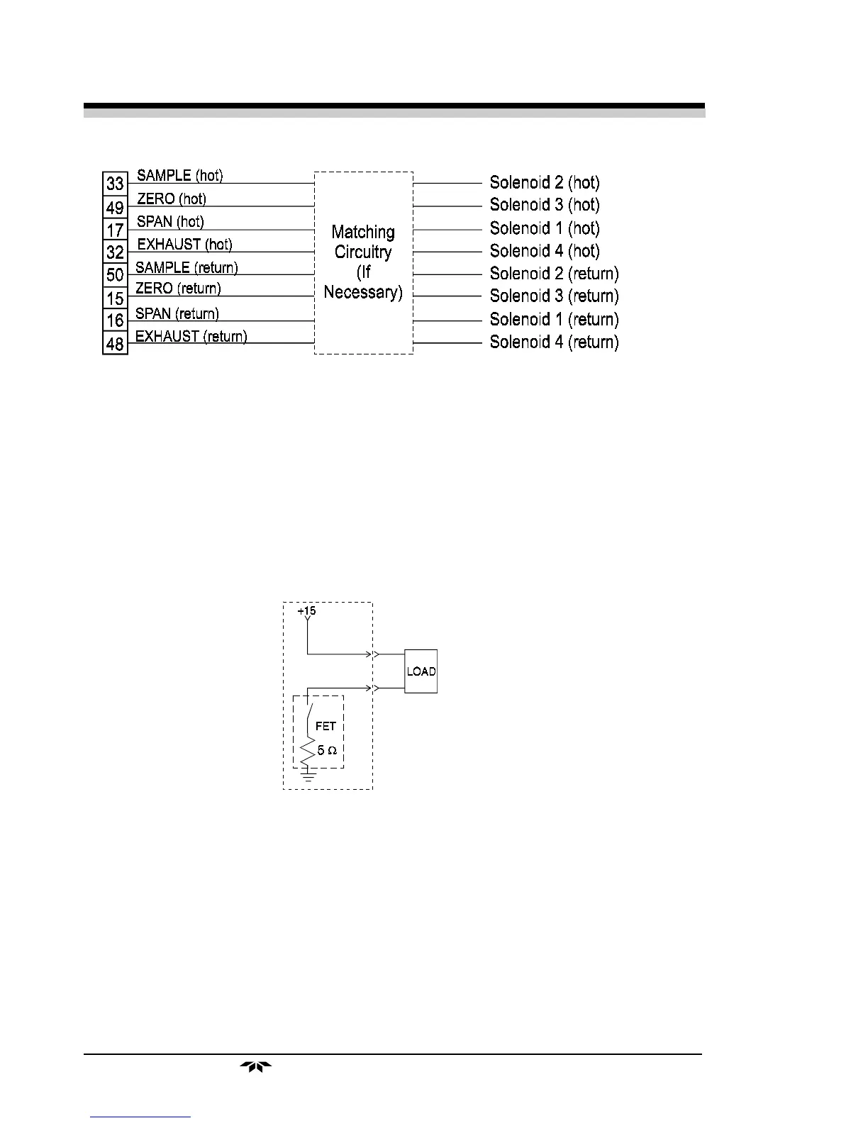
Figure 3-5: Remote Probe Connector Pinouts
The voltage from these outputs is nominally 0 V for the OFF and
15 V dc for the ON conditions. The maximum combined current that can
be pulled from these output lines is 100 mA. (If two lines are ON at the
same time, each must be limited to 50 mA, etc.) If more current and/or a
different voltage is required, use a relay, power amplifier, or other match-
ing circuitry to provide the actual driving current.
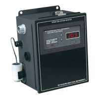
In addition, each individual line has a series FET with a nominal ON
resistance of 5 ohms (9 ohms worst case). This could limit the obtainable
voltage, depending on the load impedance applied. See Figure 3-7.
Figure 3-6: FET Series Resistance
3.3.4 RS-232 Port
The digital signal output is a standard RS-232 serial communications
port used to connect the analyzer to a computer, terminal, or other digital
device. It requires a standard 9-pin D connector.
Output: The data output is status information, in digital form, up-
dated every two seconds. Status is reported in the following order:
• The concentration in ppm or percent