Do you have a question about the Teledyne MB1 and is the answer not in the manual?
Documents critical safety warnings and cautions for system operation.
Explains the MB1 system architecture and its constituent parts.
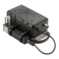
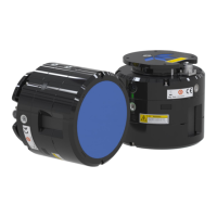
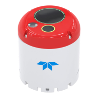
Details the functions and features of the MB1 sounder unit.
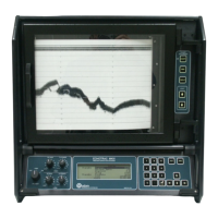
Describes the RTA's role as the system's interface and control unit.
Explains the function and specifications of the MB1 power and data cable.
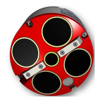
Describes the optional mounting plate for the MB1 sonar.
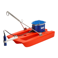
Details the optional Digibar V sound velocity probe and its integration.
Outlines the recommended power supply requirements for the MB1 system.
Lists various system configurations and sensor options.
Details the physical structure and components of the MB1 sounder.
Explains the use and benefits of the internal motion sensor.
Provides instructions for cleaning and maintaining the sounder unit.
Offers guidance on safe handling procedures to prevent damage.
Details the RTA's interface, connections, and operational features.
Describes the status LEDs and controls on the RTA's front interface.
Details the various connectors and ports on the RTA's rear panel.
Explains the DC power input connector on the RTA.
Describes how to connect the 1PPS timing signal to the RTA.
Details the GPS input connector and NMEA data formats.
Explains the heading input connector and NMEA HDT format.
Describes the input for heave, pitch, and roll data.
Details the configuration of the optional internal GPS heading board.
Guides on setting up RTA dipswitches for GPS operation.
Describes the cable for power and data transmission between RTA and sounder.
Provides instructions for maintaining the power/data cable.
Details the methods for physically mounting the MB1 sonar unit.
Explains mounting using top housing threaded holes.
Explains mounting using base housing threaded holes.
Guides on using the optional universal mounting plate.
Provides instructions for mounting the optional Digibar V probe.
Details the process of connecting external sensors to the RTA.
Outlines the steps for powering up and verifying the system.
Explains how to configure the RTA through the control software.
Details measuring and entering sensor offsets for accurate survey data.
Guides on how to assemble the optional MB1 system fairing.
Lists the necessary tools and parts for fairing assembly.
Describes connecting cables during fairing assembly.
Details attaching the rear section of the fairing.
Guides on attaching the rear top section of the fairing.
Details attaching the front section of the fairing.
| Type | Multibeam Echosounder |
|---|---|
| Depth Rating | 300 m |
| Maximum Depth | 300 m |
| Number of beams | 256 |
| Swath coverage | 140° |
| Operating Temperature | -5°C to 40°C |
| Frequency | 200 kHz |
| Swath Width | 4x water depth |
| Resolution | High |
| Power Supply | 24-48 V DC |
| Beam Width | 0.5° x 0.9° (across x along) |