Portable Oxygen Monitor
Teledyne Analytical Instruments vii
List of Figures
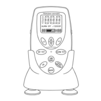
Figure 1-1: MX300 Front View ......................................................... 1
Figure 2-1: Installing the R17MED Sensor ...................................... 8
Figure 2-2: Sensor Cable Connection to Monitor ............................ 8
Figure 2-3: Mounting the Sensor in the Tee Adapter ....................... 9
Figure 2-4: V-Mount Adapter Installation ......................................... 9
Figure 2-5: Brass Insert for Universal Mounting Clamp ................. 10
Figure 2-6: Installing Batteries ....................................................... 11
Figure 2-7: Calibration Sequence .................................................. 12
Figure 2-8: Setting the Alarms ....................................................... 14
Figure 2-9: 0-1 VDC or RS 232 Digital Output Port ....................... 15