Do you have a question about the Teledyne T3DSO1000A Series and is the answer not in the manual?
Steps to set up the oscilloscope before initial operation, including physical setup and connections.
Guidance on connecting the oscilloscope to the mains power source using the provided power cord.
Procedure for powering on the oscilloscope and verifying the startup process and welcome screen.
Steps for connecting a passive probe to the oscilloscope's input channel and circuit.
Procedure to verify basic oscilloscope functionality by checking waveform display.
Instructions for compensating oscilloscope probes to ensure accurate vertical measurements.
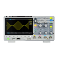
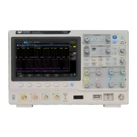
Identifies and describes the main controls and indicators on the oscilloscope's front panel.
Identifies and describes the connectors and ports located on the rear panel of the oscilloscope.
Details the functionality of key controls and menus on the front panel, including Horizontal, Vertical, and Trigger.
Explains the operation of controls related to the horizontal time base, position, and zoom functions.
Explains the operation of controls for adjusting vertical scale, position, coupling, and math functions.
Instructions for setting the vertical scale (Volts/division) for optimal waveform display.
Configuring the oscilloscope to match the probe's attenuation factor for accurate voltage readings.
Procedure for adjusting the horizontal time base (time/division) to view signal details.
Managing waveform acquisition using Run/Stop and Single buttons for continuous or single-shot captures.
Selecting the signal source (Analog Channels, EXT, AC Line) for triggering the oscilloscope.
Understanding and setting the trigger mode (Auto, Normal, Single) for waveform capture.
Adjusting the trigger level to define the voltage threshold for detecting events.
Introduction to various advanced trigger types available for capturing specific signal events.
Triggers based on the slope (rising, falling) and level of a signal edge.
Setup, triggering, and decoding procedures for I2C serial communication signals.
Configuring trigger conditions for I2C Start, Stop, Restart, No Ack, EEPROM, and data patterns.
Procedures for decoding I2C signals, including display and list views.
Setup, triggering, and decoding procedures for SPI serial communication signals.
Configuring trigger conditions for SPI data length, bit order, and specific data values.
Procedures for decoding SPI signals, including display and list views.
Setup, triggering, and decoding procedures for UART/RS232 serial communication signals.
Configuring trigger conditions for UART/RS232 Start, Stop, Data, and Error events.
Procedures for decoding UART/RS232 signals, including display and list views.
Setup, triggering, and decoding procedures for CAN serial communication signals.
Configuring trigger conditions for CAN Start, Remote, ID, ID+DATA, and Error frames.
Procedures for decoding CAN signals, including display and list views.
Setup, triggering, and decoding procedures for LIN serial communication signals.
Configuring trigger conditions for LIN Break, ID, ID+DATA, and Data Error events.
Procedures for decoding LIN signals, including display and list views.
Steps to select and display automatic measurement parameters on the oscilloscope screen.
Procedures for saving oscilloscope settings to internal memory and recalling them later.
Instructions for saving and recalling data to/from an external USB storage device.
Performing self-calibration to ensure optimal instrument performance and measurement accuracy.
Procedure for updating the oscilloscope's firmware or configuration files via USB flash drive.
Setting up and performing pass/fail tests to verify waveform compliance against defined parameters.
Details on configuring AWG settings such as output load, sync output, OVP, and zero adjust.
Configuring parameters for Bode Plot measurements, including AWG I/O, Sweep, and display settings.
Information on restoring the oscilloscope to its original factory default configuration.
| Brand | Teledyne |
|---|---|
| Model | T3DSO1000A Series |
| Category | Test Equipment |
| Language | English |