Do you have a question about the Teledyne T700U and is the answer not in the manual?
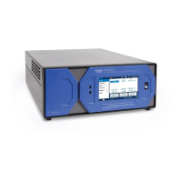
Presents the T700 Dilution System and Electrical/Physical specifications, detailing parameters like flow accuracy, response time, and I/O.
Covers procedures for unpacking, inspecting for damage, and initial setup, including safety cautions.
Presents procedures for making electrical and pneumatic connections for instrument setup and operation.
Details how to make electrical connections, including power, analog outputs, status outputs, control inputs/outputs, and interfaces.
Details connections for Ethernet, USB, RS-232, RS-232 Multidrop, and RS-485 interfaces.
Details the pneumatic connections required for instrument setup, including diluent and calibration gas.
Covers procedures for instrument startup, performing functional checks, and initial calibration.
Explains warning messages that may appear during startup and how to investigate their causes.
Details how to verify instrument operation and check parameters against factory values using test functions.
Guides on setting the total gas flow rate, which affects individual gas and diluent flow rates for mixture creation.
Explains how to generate desired calibration gas mixtures using various gas types and optional O3 generator.
Details the simplest procedure for generating calibration gas mixtures by selecting gas type, target concentration, and total flow.
Describes manual generation for more control, allowing user to set component gas flow and diluent airflow rates.
Covers performing Gas Phase Titration (GPT) calibration for NO2 mixtures using the O3 generator.
Explains the GPT Pre-Set feature for determining O3 generator output and setting parameters for subsequent GPT operations.
Covers setting up automatic calibration sequences consisting of multiple steps, initiated by various methods.
Guides on programming calibration sequences by defining attributes like name, repeat count, steps, and progress mode.
Details how to insert various instruction steps like GENERATE, GPT, GPTPS, PURGE, STANDBY, DURATION, EXECSEQ, CC OUTPUT, and MANUAL.
Introduces the communications setup menu for configuring Ethernet, COM ports, and USB for remote operation.
Groups diagnostic tools for troubleshooting, focusing on test channel analog output configuration and calibration.
Details configuring communication modes, setting baud rates, and testing serial ports for correct connection.
Explains connecting the calibrator to networks via Ethernet for remote access and configuration.
Describes how to access and calibrate MFC outputs using a table of control points and drive voltages.
Covers verifying and calibrating the optional O3 photometer's performance for accurate mixture analysis.
Details the procedure for calibrating the O3 generator, including setup and automatic calibration routines.
Explains how to calibrate the T700's internal gas pressure sensors using external pressure meters.
Outlines periodic maintenance procedures to ensure accurate and reliable operation of the T700.
Provides detailed steps for performing an automatic leak check, including equipment required and setup.
Describes a systematic approach to troubleshooting, including noting warning messages and checking test functions.
Explains how the T700 alerts users to active warning messages and how to view or clear them.
Details using test functions to isolate operational problems by comparing values to factory data sheets.
Explains how to use internal LEDs on the CPU, Relay PCA, and Valve Driver PCA for troubleshooting.
Guides on checking individual components or subsystems to determine the cause of problems.
Provides troubleshooting steps for RS-232 connections, including cabling and protocol configuration.
Focuses on troubleshooting dynamic problems with the optional O3 photometer, especially noisy readings.
Addresses troubleshooting for the O3 generator, primarily focusing on the UV source lamp and its power supply.
Explains the fundamental principles of dynamic dilution calibration using bottled gases and MFCs.
Details the operation of the O3 generator, including principles of photolytic generation and pneumatic/electronic aspects.
Explains the operation of the T700's optional photometer for determining Ozone (O3) concentration.
Details anti-ESD procedures for working on analyzers, including at instrument racks and work benches.
| Model | T700U |
|---|---|
| Manufacturer | Teledyne |
| Category | Test Equipment |
| Linearity | ±1% of full scale |
| Power Requirements | 100-240 VAC, 50/60 Hz |
| Response Time | 60 seconds |
| Zero Drift | <1% per month |
| Span Drift | Less than 0.1% of full scale per 24 hours |
| Operating Temperature | 5 to 40 °C |