Do you have a question about the Teledyne T700 and is the answer not in the manual?
Describes safety alert symbols and their meanings to prevent injury and instrument damage.
Details TAPI's warranty policy, coverage, and service availability.
Outlines procedures for product return and conditions that may void the warranty.
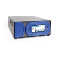
Provides a general description of the T700 calibrator's functions and features.
Lists the exceptional features and available options for the T700.
Lists the detailed technical specifications for the T700 system, including electrical and physical details.
Presents compliance statements for safety and electromagnetic compatibility directives.
Steps for unpacking, inspecting, and preparing the instrument for operation.
Describes the front and rear panel layouts and their components.
Instructions for making electrical and pneumatic connections.
Detailed procedures for all electrical connections including power, outputs, and communications.
Guidance on connecting gas sources and pneumatic system setup.
Explains RS-232 communication principles and DTE/DCE setup.
Details on selecting communication modes, baud rates, and testing ports.
Instructions for Ethernet configuration and remote access.
Using APICOM for remote control and data access.
Operating the instrument via terminal emulation programs.
Step-by-step guide for MFC calibration and verification.
Procedures for O3 photometer performance verification and calibration.
Steps for O3 generator calibration, including viewing and setting calibration points.
Outlines the typical maintenance schedule and frequency recommendations.
Detailed procedures for common maintenance tasks like leak checks and lamp adjustments.
A systematic approach for diagnosing and resolving instrument problems.
How to interpret and clear instrument warning messages.
Methods for checking the operational status of major subsystems.
Addresses common dynamic problems and troubleshooting steps for the O3 photometer.
Troubleshooting steps for the O3 generator, particularly lamp power supply.
Explains the core concepts of dynamic dilution calibration.
Describes the pneumatic system, gas flow control, and critical components.
Overview of the electronic components including CPU, Motherboard, and PCAs.
Details on the O3 generator's principles and pneumatic/electronic operation.
Explains the photometer's measurement method, absorption path, and electronic operation.
| NO Range | 0-20 ppm |
|---|---|
| NO2 Range | 0-20 ppm |
| NOx Range | 0-20 ppm |
| Power Requirements | 100-240 VAC, 50/60 Hz |
| Resolution | 0.1 ppb |
| Power Supply | 100-240 VAC, 50/60 Hz |
| Sensor Type | Chemiluminescence |
| Measurement Type | Nitrogen Oxides (NO, NO2, NOx) |
| Measurement Range | 0-20 ppm |
| Output | Analog and digital outputs |