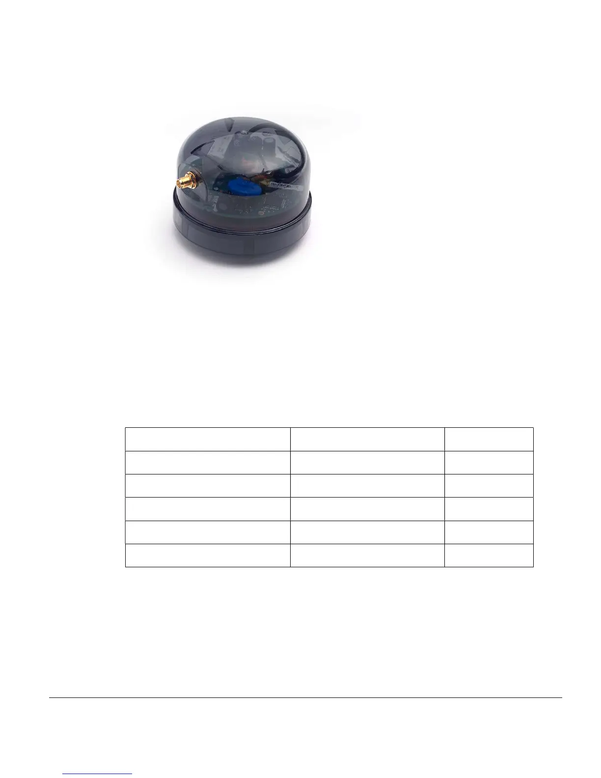
Post Top (internal, requires antenna)
The Post Top Telecell is fitted as per the plug in locking type but has an external antenna
same as the Two-Part Telecell. This Telecell is typically used where the plug in locking
type socket has been installed inside the luminaire casing.
2.2 Wiring Diagrams
For Telecells with attached wires, the wiring colours depend on the market the Telecell is
intended for, as shown here:
ETSI FCC
Live In
Brown Black
Neutral
Blue White
Switched Live Out
Red Red
dimming control positive
Purple Violet
dimming control negative
Grey Grey
The following diagrams show how the Telecells should be wired. These diagrams show
the ETSI wiring colours. For a FCC installation, substitute the colours using the table
above: