Table of RS-232 DB9 pins:
Pin
No.
Name Dir Description
1 GND - Ground
2
GPIO1 (ADC) IN/OUT
General purpose input/output. ADC range 0..3V, 10 bit resolution.
3 GPIO2 (ADC) IN/OUT General purpose input/output (high-drive 30mA). ADC range 0..3V, 10
bit resolution.
4
RTS IN
Request To Send. Raised by DTE when it wishes to send. Expects CTS
from DCE.
5 TX OUT Request To Send. Raised by DTE when it wishes to send. Expects CTS
from DCE.
6
GPIO3 (ADC) IN/OUT
General purpose input/output. ADC range 0..3V, 10 bit resolution.
7 GPIO6
(I2C_SDA)
IN/OUT
General purpose input/output. Open-drain, pull-up 2k / I
2
C data – SDA.
8 GPIO4 (ADC) IN/OUT
General purpose input / output. ADC range 0..3V, 10 bit resolution.
9
DTR IN
Data Terminal Ready. Raised by DTE when powered on. In auto-answer
mode raised only when RI arrives from DCE.
10
GND
- Ground
11 GPIO5 (ADC) IN/OUT
General purpose input/output. ADC range 0..3V, 10 bit resolution.
12
GPIO7
(I2C_SCL)
IN/OUT
General purpose input/output. Open-drain, pull-up 2k / I
2
C clock – SCL
13
GND
- Ground
14 RX IN
Receive Data (a.k.a RxD, Rx). Arriving data from DCE.
15
CTS OUT
Clear To Send. Raised by DCE in response to RTS from DTE.
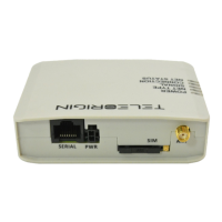
DE-15 looking into female connector:
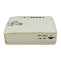
6.2.6 Power supply connector
The power supply connector is a 2-pin connector for external DC power supply
connection, which can handle voltage from range 5..30 V DC, 2.5 W max. continuous
power.
No. Singal I/O Description
+ V+BATTERY I 5 V – 30 V DC
- GND - Ground
13