EasyManua.ls Logo

Telesis TMP1700 User Manual

Telesis TMP1700
10 pages
To Next Page IconTo Next Page
Page #1 background imageLoading...
Page #1 background image
TMP1700/470 Marking System
28575G © 2009 – 2011 Telesis Technologies, Inc. – All Rights Reserved 1 of 10
SYSTEM OVERVIEW
The Telesis
®
TMP1700/470 PINSTAMP
®
marking system
permanently prints messages into a variety of materials such as
steel, aluminum, and plastic. A hardened pin is pneumatically
accelerated to indent dot matrix characters into the item being
marked. The shape, size, density, and location of characters are
determined by the user through the system software. The marking
head moves the pin cartridge through X- and Y-axis motions to
reach the correct position for each dot of the characters to be
marked. The system software automatically controls pin
extension and retraction to mark the message.
The system is compliant with UL, CSA, CE, and RoHS specifications.
TMP1700 Marking Head includes the mechanical motion
components to position the marking pin at precise X/Y positions
and the pneumatic components to drive the marking pin from, and
return the pin to, the pin cartridge.
The floating pin design permits high quality, consistent marks on
irregular, slightly curved surfaces. It also accommodates
applications where marking surfaces cannot be positioned at a
consistent distance from the marker.
The TMP1700 marking head is an X/Y-traversing mechanism.
Using two stepper motor drives, it accurately and rapidly positions
the pin at coordinate-defined locations in marking window within
.001" (.025 mm). The TMP1700 accommodates the rigorous
dynamics of impacting, rebounding, and rapid positioning of the
marking pin through a system of rigid rails and ball bearing
saddles, timing belts, and direct-drive, toothed pulleys.
The internal mechanism is protected from debris by an integral
shield. Three stainless steel panels slide against one another,
constrained by the cartridge and the high-impact ABS cover, to
prevent debris from entering the marking head. A flexible, oil-
resistant fabric boot is also available for applications requiring
additional protection, especially against liquid sprays and mists.
Marker Cable, pre-wired to the marking head, connects the
marker to the controller. The highly flexible cable is 4m (13 ft.)
long. Optional extension cables are available for greater distances.
Pin Cartridges, machined from engineered plastic materials, offer
long life with little maintenance. Clasps are used to attach the pin
cartridge to the marking head for easy cleaning and pin replacement.
Marking Pins for the TMP1700 include the 25L-, 25XL-, 150S,
150SA-series and the 10MP MicroPin™. Refer to the TMP1700
Marking Head Dimensions drawing for pin stroke (pin extension)
dimensions. Refer to the marking depth tables for pin cone angles
and depths.
Filter/Regulator Unit includes two regulators with pressure
gauges to control the drive air and return air. The first regulator
contains a filter to help remove contaminants from the supply air.
Two air lines connect the regulated air to the marking head. Drive
air fires the impact pin; return air pushes it back into the cartridge.
The standard air lines are 12 ft. (3.6 m) long made of 1/4" tubing.
TMC470 Controller contains an integrated keyboard with an LCD
display. It provides a text-only operator interface and allows full
operational control of the TMP1700 marking head. The back panel
provides the electrical interface for connecting to optional, remote
I/O sources. Refer to TMC470 Controller Specifications for details.
Optional System Computer. The TMC470 Controller may be
connected to a PC that runs the Merlin
®
III Visual Design Software.
The PC may be supplied by Telesis or by the customer. Refer to
PC-based Merlin III Software and TCP/IP Interface for details.
TMP1700/470 Marking System – General Arrangement
Question and Answer IconNeed help?

Do you have a question about the Telesis TMP1700 and is the answer not in the manual?

Telesis TMP1700 Specifications

General IconGeneral
BrandTelesis
ModelTMP1700
CategoryTools
LanguageEnglish

Summary

System Overview

TMP1700 Marking Head

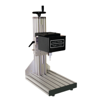
Describes the mechanical motion components for positioning and driving the marking pin.

Marker Cable

Details the pre-wired cable connecting the marker to the controller, including length and options.

Pin Cartridges and Pins

Covers pin cartridge material, attachment, and types of marking pins available.

Filter/Regulator Unit

Explains the unit's function in controlling drive and return air, including filter and pressure gauges.

TMC470 Controller

Details the controller's interface, operator control, and back panel connectivity.

Optional System Computer

Describes the connection to a PC running Merlin III Visual Design Software.

System Setup

Mounting and Air Connections

Instructions for mounting the marking head and connecting air lines to the system.

Controller and Cable Connections

Steps for connecting the controller cables and power before initial setup.

PC Integration (Optional)

Details for connecting an optional PC running Merlin III Visual Design Software.

Final Setup Steps

Procedures for powering on the controller and starting the marking software.

TMP1700 Marking Head Specifications

Dimensions and Weight

Provides physical dimensions and weight specifications for the marking head.

Operating Environment

Specifies the operating temperature and humidity ranges for the marking head.

Air Supply and Consumption

Details the required air supply pressure and consumption rates for operation.

Marking Area and Pin Types

Defines the marking area dimensions and compatible pin types.

Pin Material

Lists the materials used for marking pins and their associated types.

TMP1700 Marking Head Performance

Marking Characteristics

Describes character size, resolution, and depth adjustment capabilities.

Marking Speeds

Details the marking speed and factors affecting it.

Pin Life

Estimates pin lifespan based on material hardness and marking depth.

Marking Noise

Reports measured noise levels and factors influencing sound exposure.

TMP1700 Marking Depth and Vibration

Marking Depth Tables

Provides sample marking depths for various pin types and materials.

Vibration Data and Exposure Values

Presents vibration test results and exposure limit values.

TMC470 Controller Overview

Controller Specifications

Lists compliance, configurations, rating, dimensions, and weight.

Operating and Power Specs

Details operating temperature, humidity, cooling, power, and communication interfaces.

Input and Output Signals

Describes the controller's optically isolated input and output signals.

TMC470 Controller Dimensions and Mounting

Controller Dimensions Overview

Provides diagrams and measurements for controller dimensions.

Panel-mounted Configuration Details

Illustrates cutout and hole details for panel-mounting the controller.

TMC470 Environmental and EMI Considerations

Environmental Contaminant Protection

Addresses NEMA rating and protection needs in contaminated environments.

EMI Susceptibility Management

Provides guidance on managing electromagnetic interference during installation.

TMC470 Software and PC Integration

TMC470 System Software

Explains the controller's built-in software for pattern storage and operation.

PC-based Merlin III Software

Describes the PC software for pattern design, editing, and system control.

TMC470 Controller Interface Ports

Serial and Discrete I/O Ports

Details serial (Comm 1/2) and discrete I/O port functionalities.

TTL, TCP/IP, and USB Ports

Explains TTL, Ethernet (TCP/IP), and USB port uses.

Auxiliary Axis Port

Describes the port for connecting optional motion devices.

TMC470 Discrete I/O Controls

Input Signal Functions

Lists input signals for remotely controlling marker operations.

Output Signal States

Describes output signals indicating system status.

Host Communications

Communication Interfaces

Overview of RS-232, RS-485, and TCP/IP interfaces for host communication.

Serial Data Format

Defines the asynchronous serial data character format.

TCP/IP Interface Requirements

Details PC requirements for connecting via TCP/IP and Merlin III software.

Host Communication Protocols

Programmable Protocol

Describes protocol for simple one-way communications with error checking.

Extended Protocol

Details protocol for applications requiring error checking and acknowledgment.

Message Type Definitions

Explains message types for data transfer and pattern loading.

Extended Protocol Message Format

Message Structure

Defines the structure of Extended Protocol messages (SOH, TYPE, STX, DATA, ETX, BCC, CR).

Message Type Details

Explains specific message types (1, P, Q, V, O, G, I) and their functions.

Status Signal Interpretation

Details how to interpret status bits for READY, DONE, PAUSED, NO FAULT.