Eclipse 8/16/32/99 Series - Installation Manual
22
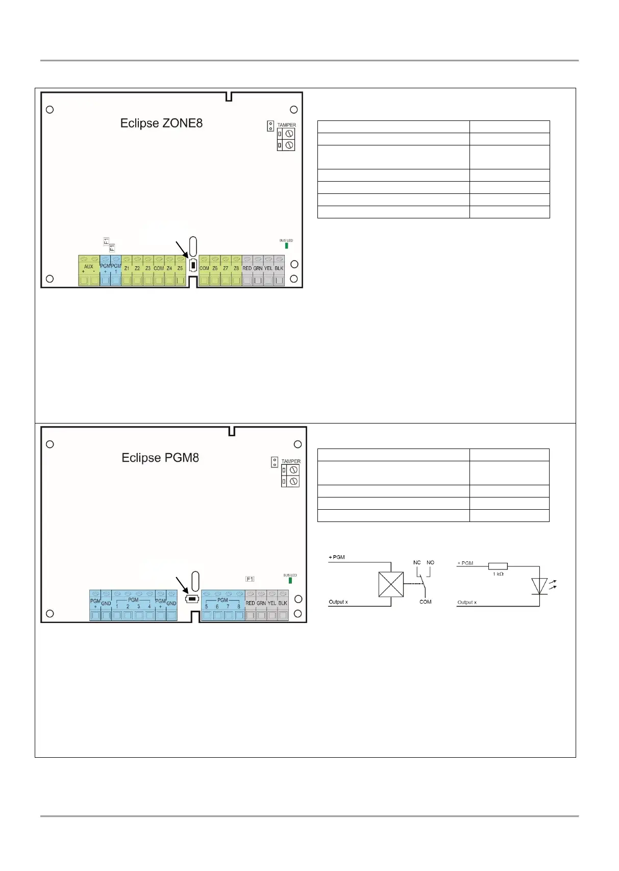
• Expanders’ Terminals and Specifications
+/- AUX – Power supply for detectors with consumption up to 0.1А.
+PGM – Power supply for auxiliary devices with consumption up to 0.75А.
PGM 1 – Programmable output, 100mA, ОС type (open collector).
Z1-Z8 – Zone inputs. Every input is independent full functional zone with freely programmable parameters. Every
additional input must be attached to a zone on the control panel.
COM – Common ground for the zones.
R(red), G(green), Y(yellow), B(black) - System bus interface for connection to control panel.
Tamper – Terminals for Tamper switch. Set a jumper on the terminals if the tamper switch is not used.
F1 – Fuses for PGMs output, 100mA.
Button – Button for enrollment of the module to the system configuration.
+PGM – Power supply for auxiliary devices with consumption up to 0.1А.
PGM 1-8 – Programmable outputs, 100mA, ОС type (open collector). Every output is independent full functional
PGM with freely programmable parameters. Every additional output must be attached to a PGM number on the
control panel.
GND – Common ground for the outputs.
R(red), G(green), Y(yellow), B(black) - System bus interface for connection to control panel.
Tamper – Terminals for Tamper switch.
F1 – Fuse for PGM output, 100mA.
Button – Button for enrollment of the module to the system configuration.
Technical Specifications:
Power Supply from the panel
PGM output, 100mA, OC type
* In conformity with the requirements for
EN 50131-1:2006 and EN 50131-3:2009.
Technical Specifications:
PGM outputs, 100mA, OC type
Internal structure of PGM output: