Eclipse 8/16/32/99 Series - Installation Manual
8
2.1.2 ECLIPSE 32/99
ECLIPSE 32/99 Alarm Control Panel is mounted in a white plastic box with dimensions 335 x 290 x 105mm. There are
additional spaces for mounting of one communication module in the box and one expander module (under the main
PCB). For the back-up battery is provided special place. The box is equipped also with a transformer unit and 230V
connection terminal with protective fuse.
The front cover is fixed with two mounting screws and nuts provided in the spare parts kit.
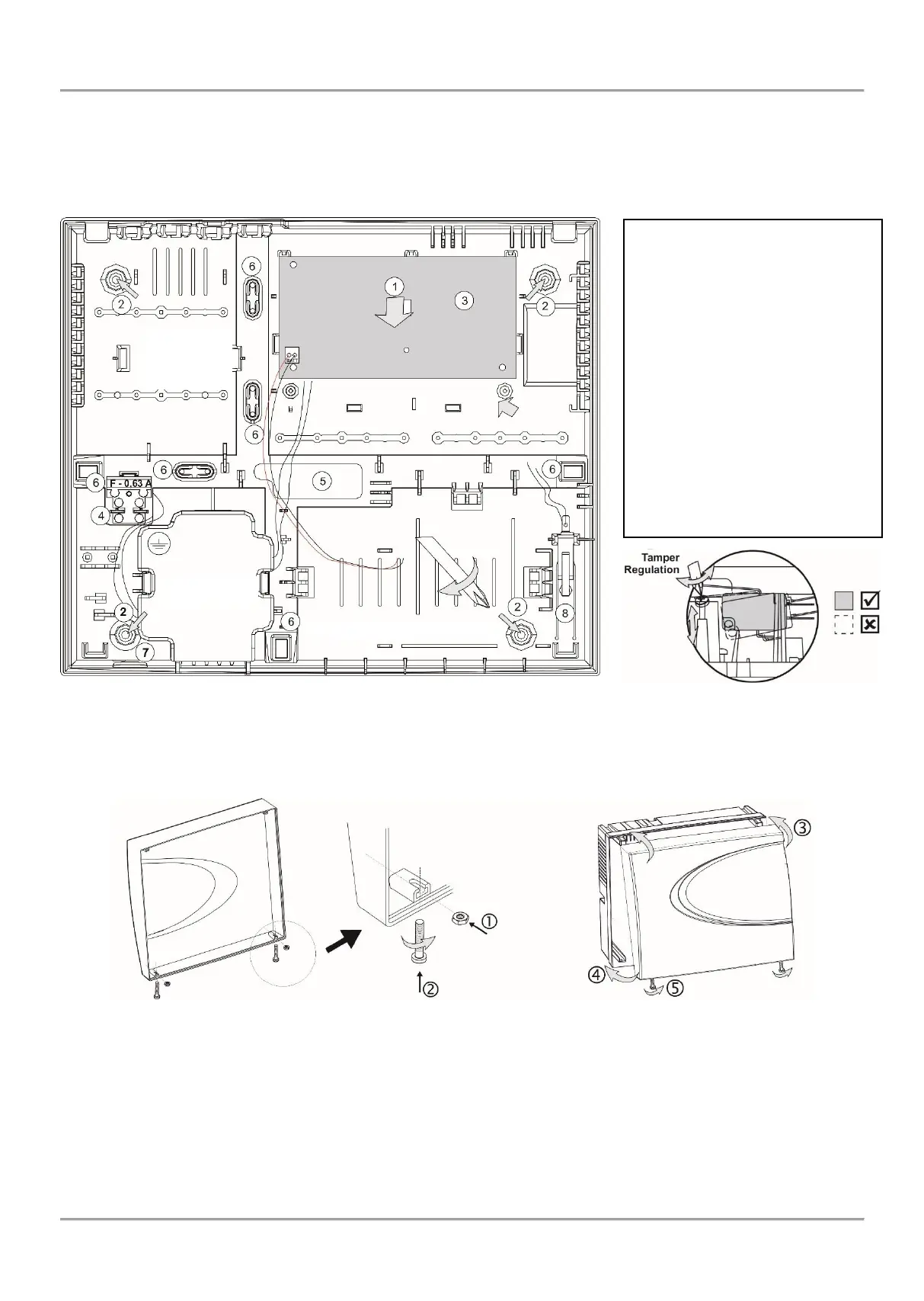
Figure 3. ECLIPSE 32/99 box elements
In ECLIPSE 32/99 final closing, use the supplied screws and nuts in the spare parts kit to fix the front cover to the
mounted bottom.
- Put the nuts into the nests on the backside of the front cover;
- Take the screws with interrupted thread and screw on them into the openings at the front cover bottom
until the nut and the interrupted part come together.
- Fix the front cover onto the mounted bottom;
- Close the cover;
- Screw on the screw for final closing.
Figure 4. ECLIPSE 32/99 final closing
- General support opening of
the box (situated under the PCB);
- Support openings;
- ECLIPSE 32/99 control panel;
- Mains power supply terminal
with fuse 0.63A;
- Main cable opening;
- Additional cable openings;
Remove the plastic caps from the
box bottom and fix the cable with
them;
- Mains power supply opening;
- Place for mounting of tamper-
switch (the tamper-switch is not
included in the supplied
equipment).