Eclipse 8/16/32/99 Series - Installation Manual
26
• Installation of proximity reader Eclipse PR
Eclipse PR is a stand-alone proximity card reader, which is connected to the system bus of the control panel. The
reader is with compact design and is suitable for wall mounting:
All LEDs are blinking in turn – the reader is not enrolled to the system; or there is no communication with the control
panel.
All LEDs are blinking together – the system is in programming mode.
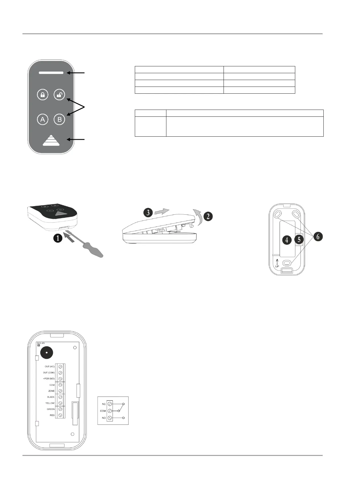
Mounting and description of the elements of Eclipse PR:
Figure 19. Proximity card reader Eclipse PR:
a) and b) Opening the box; c) Wall mounting.
1 – Open the box as use small plain screw driver
2 – Pick up the cover
3 – Slide the cover as shown on the drawing and remove it from the base
4 – Main opening for running cables
5 – Cable channel for running wires on the back side of the base
6 – Mounting holes
Description of the terminal row:
RED, GREEN, YELLOW, BLACK – System bus interface for connection to control panel
ZONE – Independent full functional zone with freely programmable parameters. It can be
used as additional zone to control panel and must be attached to a zone number at
address 2xx0 (xx is number of the zone) with the respective number of the device. It is
suitable to connect a magnetic contact to this zone (entry-exit type).
COМ – Common ground
NO/COM/NC – Relay, volt free changeover contacts: 0.5A/125VAC; 1A/30 VDC.
Internal structure of the relay:
Bus LED – LED indication for the status of the system bus; in normal operation mode the
LED is blinking evenly in green.