iRIS4 - Addressable Fire Alarm Panel – Installation Manual
15
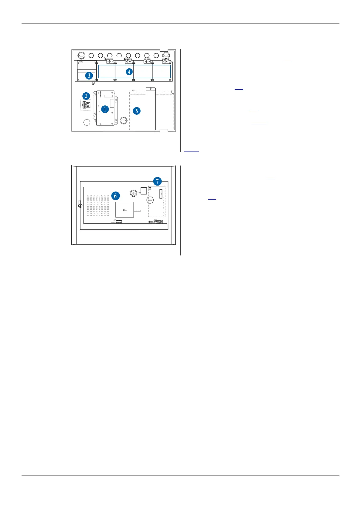
3.3. Configuration of the Basic Modules
The iRIS4 panel is designed with a range of basic modules organized in factory configuration – Figure 14.
Elements’ description:
1 - Main power supply unit - see item 4.1.
2 - Terminal for connection between the
main power supply and a power source.
A slow type fuse 2A is situated into the
terminal - see item 4.1.
3 - Monitored Outputs Control Module
with suplementary, factory mounted,
Relay Module - see item 4.2.
4 – Place for mounting of Loop
expanders 1-4 - see item 4.3.4.
5 - Place for accumulator battery
12V/18Ah or 12V/17Ah with vertical
supporting tightening clamp - see item
4.1.2.
Back side of the front door
6 - Main (Indication LCD and LED)
control module PCB - see item 4.4.
7 - Opening for changing the text label
with description of the system status -
see item 3.2.
(Note: iRIS4 panels are delivered with
printed PVC text labels in different
languages. The labels are cut with the
pointed out dimensions and are easily
replaced during the installation.)