iRIS4 - Addressable Fire Alarm Panel – Installation Manual
20
L
C
- is the necessary length of the cable for the loop.
After calculating, the maximal length of the cable is determined according:
·
If L
C
≤ L
C2max
and L
C
≤ L
C3max
- the fire panel will be able to communicate with the devices in the loop and also will
be able to identify the presence of double address.
·
If L
C2max
< L
C
≤ L
C1max
and L
C
≤ L
C3max
- the fire panel will be able to communicate with the devices in the loop but
will not be able to identify the presence of double addresses.
ATTENTION: Always calculate the maximal cable length according the mentioned above formulas!
IF L
C
> L
C1max
or L
C
> L
C3max
- the fire panel would not be able to communicate with the devices.
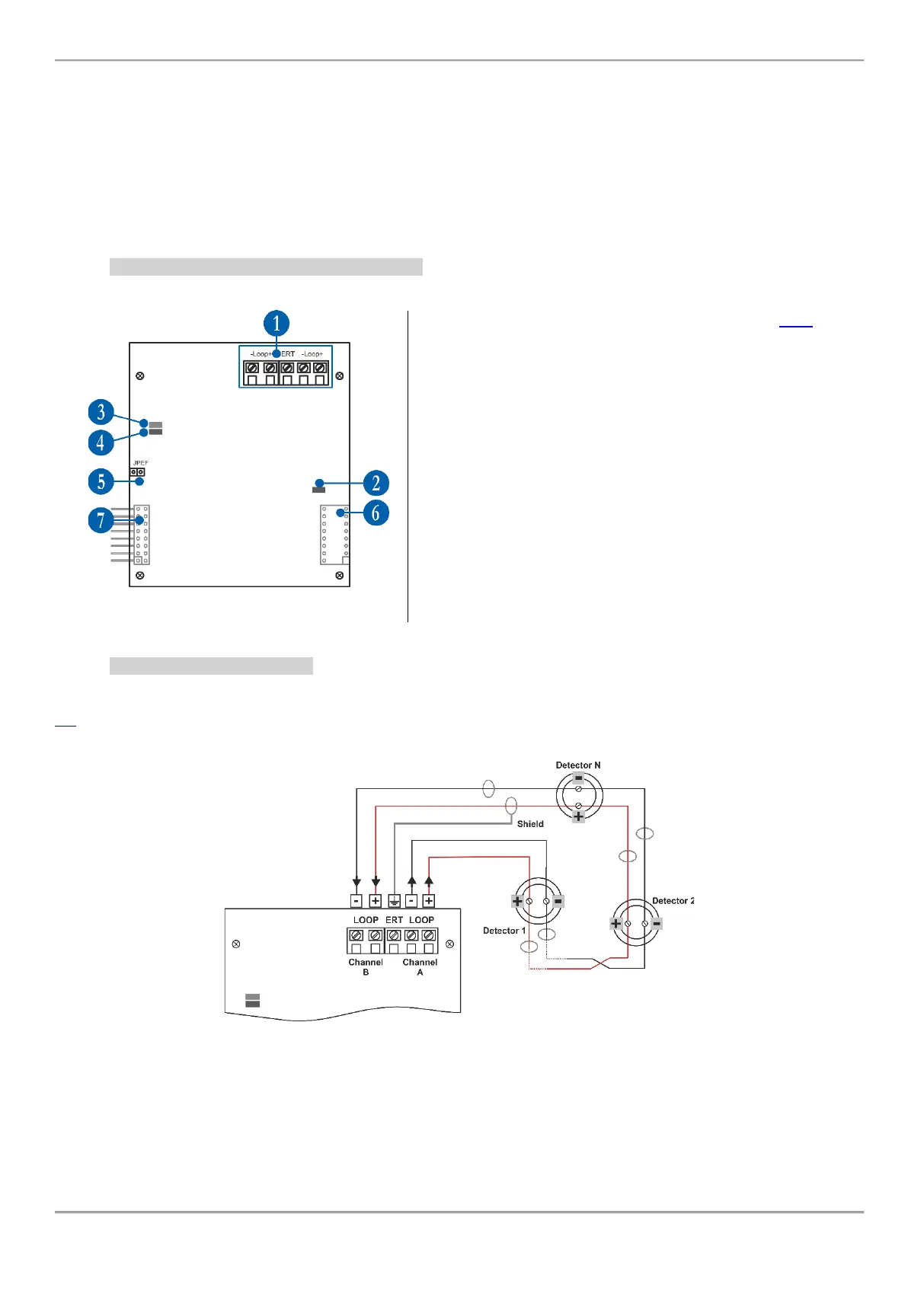
4.3.2. Loop Expander Elements Description
1 - Interface for connection of the loop line – see item 4.3.3.
2 - LED (red) – Indication for power supply of the Loop
expander. In normal operation mode it is constantly lighting on.
3 - LED (green) – Indication for data transfer between the main
microprocessor of the panel and the Loop expander. In normal
operation mode it is constantly blinking.
4 - LED (red) – Indication for scanning the devices connected
to the Loop expander. In normal operation mode the LED
lights on continuously in 10 seconds intervals.
5 - Jumper for enable/disable indication for earth fault (JPEF).
For example, if you want to enable the earth fault indication set
a jumper.
6 - Interface connector for connecting the next Loop expander
(on the back side of the Loop expander).
7 - Interface connector for connecting the Loop expander to
the Output Module or to other (previous in order) loop
expander (on the back side of the Loop expander).
4.3.3. Loop Line Connection
Connect the loop line to the iRIS8 Loop expander as strictly observe the polarity. The “Channel A” is the starting point
for addressing the connected devices, and “Channel B” is the end point. The addressing methods are described in item
5.2. To avoid faults and malfunctioning of the system, the loop line must be connected to the Loop expander only
when the main and back-up supplies of the panel are off!
Figure 21