2
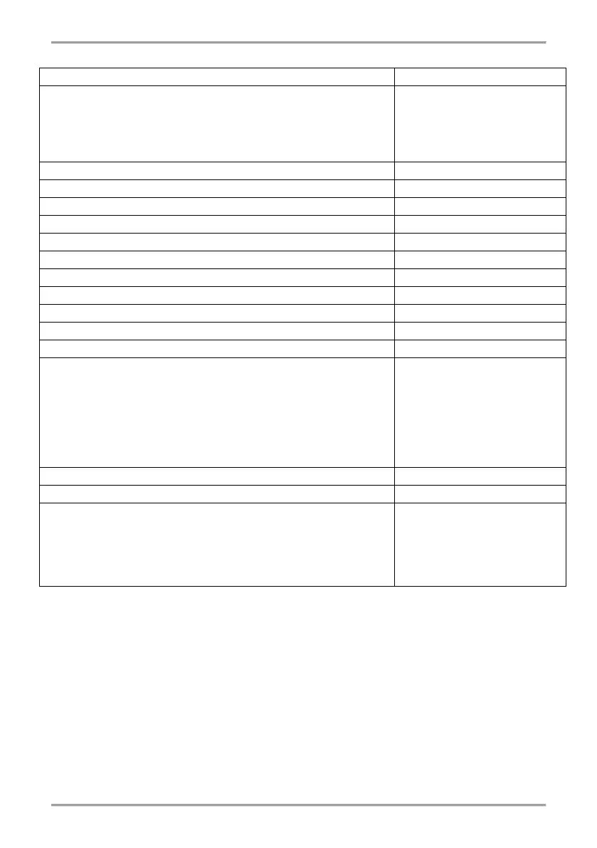
3. Technical Specifications
Power supply (External power supply unit, EN 54 compatible)
Consumption:
- Nominal consumption, LCD display ON
- Nominal consumption, LCD display OFF
- Max. consumption, LCD display ON
- Max. consumption, LCD display OFF
17mA@24V DC
14mA@24V DC
19mA@20V DC
15mA@20V DC
Radio signal modulation type
Number of frequency channels
Receiver category (EN300-220-1)
Max. connected wireless modules to a conventional panel*
Max. enrolled wireless devices to a wireless module
Communication range with Natron wireless devices (open space**)
Antenna:
- Type
- Frequency
- Impedance
- Type of Radiation
- Gain
- Connector type
- Dimensions
Dipole antenna
866-870MHz, Center 868Mhz
50Ω
Omni-directional
2 dBi
SMA Male (Swivel)
242x12.5mm
Related humidity resistance (no condensation)
Enclosure box:
- Material
- Dimensions
- Color
- Protection
- Weight (with mounted PCB and antenna)
ABS
191x125x60mm
RAL 7024 (graphite grey)
IP66/68
~ 200g
* Depends on system/control panel capacity
** Depends on system/control panel capacity and building structure
4. Installation Place and Mounting
It is strongly recommended to design the Natron wireless system in advance on paper, before
starting the installation. Natron WE-C expander (network gateway) module should be installed at
2-2.5m above the floor level.
Attention: Avoid installation of Natron WE-C module and the wireless devices near to:
• Power lines or other high voltage equipment with large electric consumption.
• Big metal structures – cabinets, pending ceilings, thick concrete walls. Note that, the quality
of the signal strength is reduced with 80%, and sometimes with 100% (full reflection) in
premises with metal walls or surfaces.
• Fluorescent lamps and lighting fixtures.
• Wi/Fi Routers, wireless telephone stations, computers and network cabling.