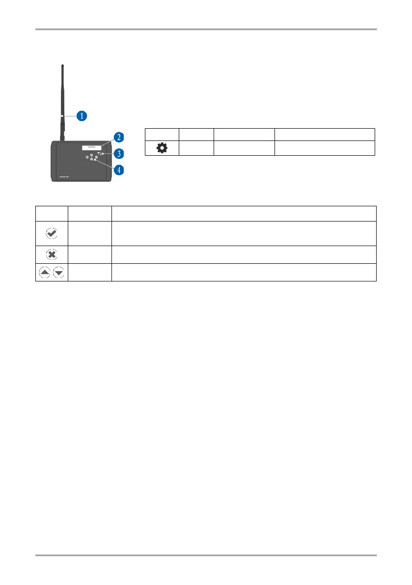
1 – Antenna (mounted to the antenna connector on the PCB).
2 – LCD text display, dot matrix 16x2.
3 – LED indication for the module status:
9. Initial Power-up of Natron WE-C
1. Switch off the main and back-up power supply of the conventional fire alarm panel.
2. Open the enclosure box of the expander (network gateway) module and mount it on the place
of installation – see item 4.
3. Connect Natron WE-C module at the end of the conventional zone line and at the end of
sounders circuit – see item 7.
4. Connect the external power supply unit to “±PW” terminals of the module.
5. Switch on the main and back-up power supply of the conventional panel.
6. Switch on the external power supply unit of Natron WE-C.
7. Mount the antenna and enroll wireless devices to Natron WE-C expander (network gateway)
module – see item 11.
8. Program the wireless devices parameters according the requirement of the fire installation –
see item 14.
8. Close the enclosure box of the module. Set the position of the antenna for best signal strength
and coverage – see item 4.
10. Check the signal strength of every wireless device and test its operation in case of fire alarm
condition – see item 15.
11. Reset the conventional fire alarm panel after the adding and testing of wireless devices is
complete.