5
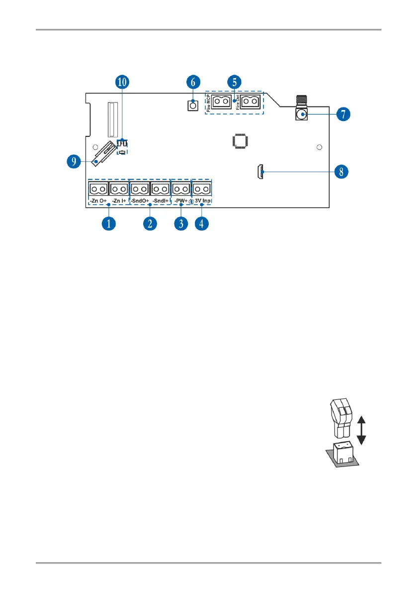
6. PCB Elements
To access the PCB of the module, open the enclosure box (follow the steps described in item 4).
The PCB is factory mounted at the back side of the front cover.
1 - Terminals for connecting the conventional zone line - item 7.2.
2 - Terminals for connecting the sounders’ circuit - item 7.3.
3 - Terminals for connecting the power supply unit - item 7.1.
4 - Terminals for monitoring the power supply - item 7.1.
5 - Terminals for connecting EOLs for zone alarm - item 7.4.
6 - Button for entering the menus for programming and settings.
7 - Antenna connector.
8 - Micro USB for reading the configuration with ProsTE software.
9 - Tamper button for self-protection of the module’s box.
10 - LED indicators – see the detailed description in item 8.
7. Wiring the Electrical Circuits
Attention: All wiring connections between wireless expander (network gateway) module
and conventional fire alarm panel must be done with switched off main and back-up power
supply units of both devices!
The module is equipped with 2-position plug terminals for easy wiring of all
electrical circuits. To make a connection, just pick up the plug to dismount it
from the PCB terminal. Make the wiring observing the polarity according the
connection diagrams presented further in this installation manual. Then mount
back the 2-position plug to the PCB terminal.