Do you have a question about the Teltonika FMB125 and is the answer not in the manual?
Safety instructions and warnings for device handling and installation.
Guidelines for safe operation, voltage limits, and environmental considerations.
Copyright information, reproduction rights, and manufacturer's reservation of changes.
Information on the document's scope, architecture, and acronyms used.
Lists the items included in the FMB1YX device package for operation.
Details GSM/GPRS/GNSS features, hardware capabilities, and interface specifics for different models.
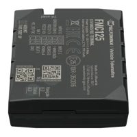
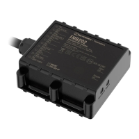
Detailed specification table including part name, physical spec, and technical details.
Details of the Li-ion rechargeable battery specifications and disposal instructions.
Electrical characteristics including supply voltage, digital output, and analog input specifications.
Table listing the absolute maximum ratings for the device's electrical characteristics.
Step-by-step guide for SIM card insertion and removal, including safety notes.
Instructions for inserting a MicroSD card into the device.
Software requirements and download links for installing necessary device drivers.
Detailed pinout description and connection schemes for FMB120 and FMB122 models.
Detailed pinout description and connection schemes for FMB125 model.
Information on available accessories and their connection schemes.
Explains how the module acquires and sends records using GNSS and I/O data.
Describes the three sleep modes: GPS, Deep, and Online Deep Sleep.
Explains the virtual odometer for calculating traveled distance and trip data.
Overview of features to enhance FMB1YX usability.
Helps prevent harsh driving by monitoring acceleration, braking, and cornering.
Prevents exceeding speed limits and inspects driver behavior.
Detects GSM signal jamming and controls digital output.
Customizable feature for monitoring trips, logging points, and calculating eco score.
Activates Digital Output (DOUT) upon receiving an incoming call.
Scenario for vehicle security, requiring iButton connection for operation.
Notifies when an iButton is read, turning on DOUT for a configured duration.
Calculates fuel consumption based on set values in different situations.
Features that utilize the accelerometer for detecting motion and events.
Informs about stationary vehicles with running engines to save fuel.
Generates an event when the FMB1YX is unplugged or plugged back in.
Informs the driver about car deporting, towing, or lifting.
Monitors acceleration on each axis to detect accidents.
Bluetooth functionality allowing slave or master mode operation.
Activates automatically by turning off car ignition for theft prevention.
Allows detection of vehicles entering or leaving customized areas.
Used to enter authorized iButton IDs for driver authentication.
Details on how to configure the FMB1YX module using SMS commands or the configurator program.
Describes the functions of the main buttons in the FMB1YX configurator.
Commands for setting and managing configuration keywords via SMS.
How keywords are handled during TCP configuration.
Monitoring real-time information like Device, GNSS, GSM, OBD/CAN, and I/O status.
Information on SIM card and configurator keyword security settings.
Configuration of system parameters including sleep modes and ignition sources.
Defines main parameters for GSM operator APN, GPRS username/password, and server settings.
Configuration for SMS data sending, incoming call actions, and hands-free call functionality.
Configuration of operator lists for roaming, home, and blacklist settings.
Functionality for managing two SIM cards, GPRS settings, and roaming operator lists.
User-defined configuration for how records are saved and sent based on network.
Overview of available features and GPS fuel counter settings.
Scenario activated when acceleration, braking, or cornering exceeds parameters.
Details how green driving events are generated and data is outputted.
Steps for calibrating the accelerometer for green driving functionality.
Scenario activated when vehicle speed exceeds the configured maximum speed.
Scenario activated when GSM signal jamming is detected.
Activates scenarios and digital outputs based on incoming calls from authorized numbers.
Scenario for vehicle security that controls digital output based on iButton presence.
Notifies when an iButton is read, turning on DOUT for a configured duration.
Functionality to calculate fuel consumption based on set values.
Features that utilize the accelerometer for detecting motion and events.
Informs about stationary vehicles with running engines to save fuel.
Generates an event when the FMB1YX is unplugged or plugged back in.
Informs the driver about car deporting, towing, or lifting.
Monitors acceleration on each axis to detect accidents.
Configuration of ON and OFF durations for Digital Outputs in various scenarios.
Manages DOUT control based on a non-configurable priority system.
Configures geofencing zones, activation timeouts, and deactivation sources.
Configuration of geofence zones and event generation when borders are crossed.
Configuration for trip tracking and odometer settings.
User interface for configuring the trip feature, including start speed and distance counting.
Settings for Eco Score events and iButton remember functionality.
Selection of the calculation source for odometer values (GNSS, OBD, LVCAN).
Configuration of Bluetooth settings for connectivity and device discovery.
Configures Bluetooth to work in slave mode, allowing external device connections.
Instructions for configuring FMB device Bluetooth settings for hands-free connection.
Steps to connect a Hands Free device after Bluetooth configuration.
How to retrieve device logs using a mobile phone and terminal application.
Steps for debugging the device using an Android smartphone and Bluetooth terminal.
Guide for preparing Bluetooth Dongle connection to the FMB device.
Steps to configure Bluetooth settings for connecting an OBD II dongle.
Instructions for connecting the car OBD II dongle to the FMB device.
Lists supported Bluetooth OBD II dongles based on ELM327 or STN1110 chips.
Functionality to send configured SMS messages when an event is triggered by I/O elements.
List used to enter authorized iButton ID codes for authentication.
Details on I/O properties and how they are recorded with GPS data.
Defines the priority for I/O properties (disabled, low, high, panic).
Defines when an event is sent (range exit, entrance, both, etc.).
Parameter defining the high value threshold for triggering I/O properties.
Parameter defining the low value threshold for triggering I/O properties.
Defines if an I/O element value is sent with every AVL packet or only on event.
Parameter defining the sample length for averaging I/O properties.
Enables/disables SMS event sending for configured GSM numbers.
Allows configuring the SMS event text for I/O properties.
Summary of I/O element parameters, priority, operand, and event settings.
Parameters related to OBD II (Bluetooth) functionality.
Defines OBD II property type priority (disabled, low, high, panic).
Defines when OBD II event is sent (range exit, entrance, both, etc.).
Defines high value threshold for triggered OBD II properties.
Defines low value threshold for triggered OBD II properties.
Defines if OBD II element value is sent with every AVL packet or only on event.
Enables/disables SMS event sending for configured GSM numbers.
Configures the SMS event text for OBD II I/O events.
Table listing property IDs for all OBD II I/O elements.
Parameters related to LVCAN communication.
Sets the LVCAN mode (Auto Detect, LV-CAN200, ALL-CAN300).
Enables/disables data sending with 0 value when ignition is off.
Sets the LVCAN Program number based on vehicle model.
Defines the priority for LVCAN properties (disabled, low, high, panic).
Defines when LVCAN event data is sent (range exit, entrance, both, etc.).
Defines high value threshold for triggered LVCAN properties.
Defines low value threshold for triggered LVCAN properties.
Defines if LVCAN element value is sent with every AVL packet or only on event.
Parameter defines LVCAN property sample length to average.
Enables/disables SMS event sending for LVCAN parameters.
Configures the SMS event text for LVCAN properties.
Table listing property IDs for all LVCAN I/O elements.
Configuration for RS232 and RS485 serial communication modes.
Sets the UART working mode for RS232 and RS485 communication.
Parameters and modes for RS232 communication.
Defines various working modes for RS232 communication like log, NMEA, LLS.
Configures the Baudrate for RS232 communication across different modes.
Configures the parity setting for RS232 communication (default, none, odd, even).
Settings for advanced data filtering in RS232 TCP Binary mode.
Sets Prefix 1 for advanced data filtering in RS232 TCP Binary mode.
Sets Prefix 2 for advanced data filtering in RS232 TCP Binary mode.
Sets Prefix 3 for advanced data filtering in RS232 TCP Binary mode.
Configures filtering capabilities for Garmin FMI mode (Ping and Unicode packets).
Parameters and modes for RS485 communication.
Selects RS485 working modes like log, NMEA, LLS, TCP ASCII, TCP Binary.
Configures Baudrate for RS485 communication across different modes.
Configuration of addresses for up to 5 LLS sensors.
Configures the address for the first LLS fuel level sensor.
Recommendations for connecting wires, avoiding heat and ensuring proper isolation.
Guidance on connecting the power source, including fuse usage and voltage checks.
Instructions for identifying and connecting the ignition wire correctly.
Guidelines for connecting the ground wire to the vehicle frame or designated points.
| Bluetooth | Yes |
|---|---|
| USB version | 2.0 |
| USB connector type | Micro-USB |
| Serial interface type | RS-232, RS-485 |
| Number of analog inputs | 1 |
| Purpose | Car |
| Product color | Black |
| Channels quantity | 33 channels |
| Electronic compass | - |
| GSM bands supported | 850, 900, 1800, 1900 MHz |
| SIM card capability | Dual SIM |
| International Protection (IP) code | IP41 |
| Battery voltage | 3.7 V |
| Battery capacity | 170 mAh |
| Battery life (max) | - h |
| Operating temperature (T-T) | -40 - 85 °C |
| Operating relative humidity (H-H) | 5 - 95 % |
| Certification | CE/RED, E-Mark, EAC, REACH |
| Memory card slot(s) | No |
| Sustainability certificates | RoHS |
| Depth | 65 mm |
|---|---|
| Width | 56.6 mm |
| Height | 20.6 mm |
| Weight | 55 g |