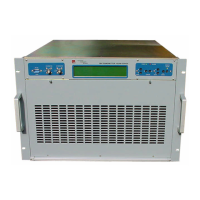
The display is explanatory enough
FREQUENCY is the output frequency set in MHz
FORW. PW is the forward output RF power
REFL. PW is the input reflected power on the RF connector
MODULATION shows the modulation value of the COMPOSITE signal
TEMPERATURE shows the radiator temperature value of the RF power final mosfet
LINE VOLTAGE shows the mains supply voltage
Moreover, in the lower part of the display, at the middle there is the indication of the number of
alarms eventually set in the memory which have taken place after the last clearing of the memory.
These ones will be displayed automatically by a continuous enter of PAGE UP.
If one enters PAGE DOWN in this screen shot, the previous one returns and it will be possible to
see once again the date of the last switching on or to change the mains supplies voltages values.
If an alarm is on, always in the same position of the display, the intermitting message ALARM will
be pointed out.
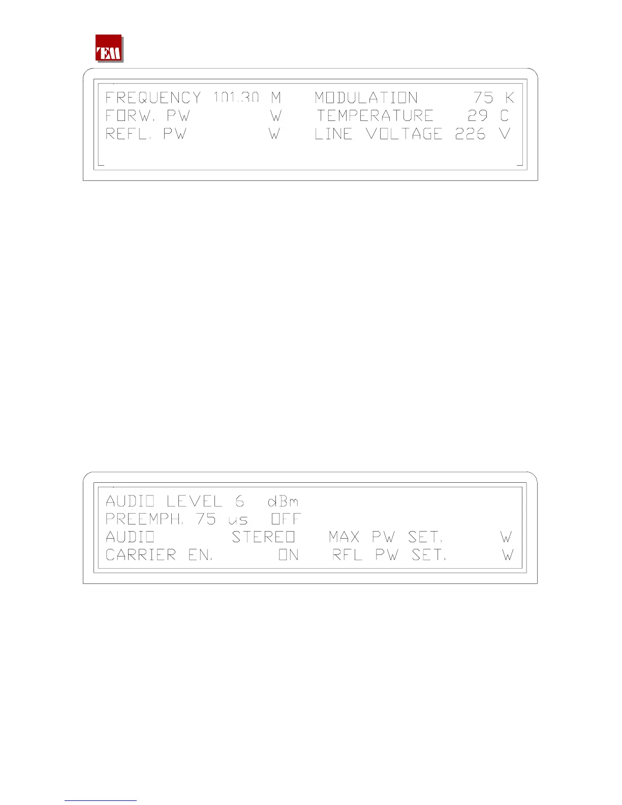
4.6.4 By entering PAGE UP, it’s possible to see the second screen shot of the most
important measures:
PA V. 48,0 48,0 48,0 48,0
PA C. 17,3 17,3 17,3 17,3
2100
100
AUDIO LEVEL
PREEMPH. 75
AUDIO
is the nominal audio signal set on the setting window placed on the
rear panel: if this value doesn't match to the needed one, it’s possible
to choose 0 , 4.1 , 6dBm or, by placing the jumper on var, it’s
possible to choose a value between –6 and +12dBm.
is the chosen pre emphasis value, always on the rear window, also the
value 50µs can be selected; the inclusion or the disabling may be
performed by the keyboard in a following screen shot.
shows whether the transmitter is set to mono or stereo.
380 221 R02 Pag. 17