A07A2200S
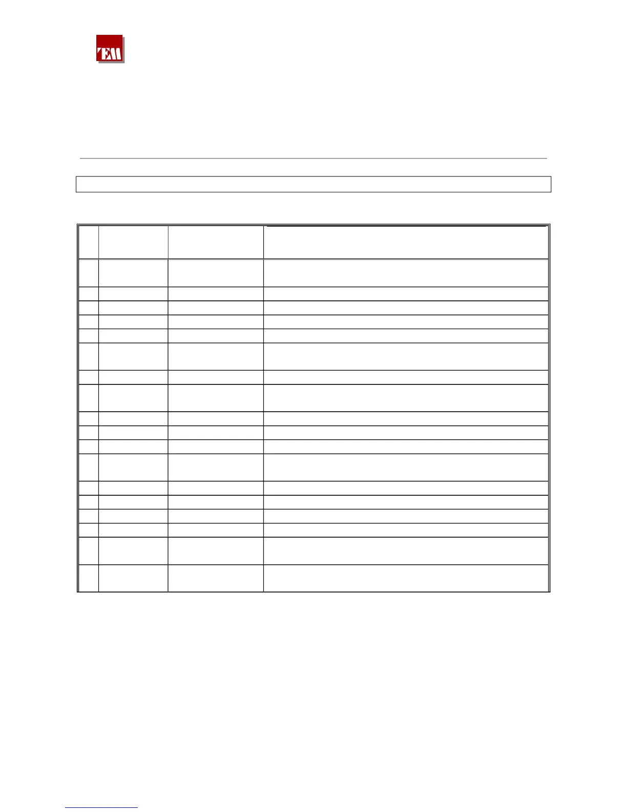
A07A2200S INTERNAL ADJUSTMENTS & SETTINGS
See figg. 9.a for function number
N°
Board name/
Component
FUNCTION
DESCRIPTION
0 MBA/RT7
MPX freqquency
deviation
Adjust, with nominal MPX input level, for 75 Khz
frequency deviation
1 DMPX/C22 Pilot frequency Adjust stereo subcarrier to 19 Khz +/-1Hz
2 DMPX/RT1 Pilot level Adjust to 20dB less than MPX signal
3 DMPX/RT3 Pilot phase Adjust to the right phase by antiphase tecnique
4 DMPX/RT2 MPX spurious Adjust for minimum spurious of MPX signal
5 DLCD/Z1 Run/Boot
Set jumper to RUN for normal operation, to BOOT for
firmware loading ( by COM1 )
6 DLCD/P9 MCU reset Press button to Reset 68HC11 microcontroller
7 DLCD/BT1 Clock battery
Use only 3.3 V lithium battery (
COMPONENT)
8 DLCD/Z2 Password Set jumper to PASSW. to enable password function.
9 MBA/RT5 Freq.dev.display Adjust to display modulation = 75 Khz on Page 0
10 MBA/RT4 Pilot THD Adjust to minimum pilot THD
11 AGC/RT1 AGC level input
Adjust, with nominal LF level input, DC voltage on DZ1 to
2.6V
12 MBA/RT1 Clipper symm. Adjust for clipper symmetry
13 MBA/RT6 Clipper level Adjust to the desired clipper level
14 MBA/RT2 Chan. Separation Adjust for max channel separation
15 MBA/RT3 Chan. Separation Adjust for max channel separation
16 SINTD/RT1
Mono frequency
deviation
Adjust, with nominal mono audiolevel in MPX input, for
75 Khz deviation
17 SINTD/CV1 Frequency
Adjust to right output frequency with fine frequency
number set to 100
380 221 R02 Pag. 50