5
Temco DV1000/1200/1400MBN Series
76658
A
B
C
10³⁄₄"
(273mm)
Min.
D
Combustible
Construction
Allowed
Firestop/Wall Sleeve
VEF (Vinyl Siding)
or BEF (Brick)
Extension Flange
Vent Terminal
2 x 4 or 2 x 6 Framing
NOTE: Maintain 2” (51mm) minimum clearance to combustibles
above vent and 1” (25mm) to sides and bottom of vent.
Standoff
Model A B C D
DV1000 15³⁄₈” Min. 30¹⁄₈”25³⁄₈”36¹⁄₈”
(391mm) (765mm) (645mm) (918mm)
DV1200 16¹⁄₂” Min. 34³⁄₄” 30” 40³⁄₄”
(419mm) (883mm) (762mm) (1035mm)
DV1400 16¹⁄₂” Min. 40³⁄₄” 36” 46³⁄₄”
(419mm) (1035mm) (914mm) (1188mm)
Fig. 3 Minimum framing dimensions with horizontal venting.
Framing and Finishing
1. Choose a fireplace location and frame in accor-
dance with the fireplace dimensions specified on
Page 4 of this manual. When using a surround, the
fireplace must be flush to the wall. Also, allowances
must be made for drywall, tile or any other facing
used around the unit.
2. When the appliance is installed directly on carpet-
ing, tile or other combustible material other than
wood flooring, the appliance shall be installed on a
metal or wood platform.
3. Pull out the nail tabs which are located on each side
of the fireplace. Move the fireplace into position and
secure to the floor with screws or nails through the
holes provided in the bottom flanges of the side
casing. After checking unit for squareness, secure
top of fireplace to the framing with screws or nails
using the nailing tabs provided.
4. Cold climate installation recommendation: when
installing this fireplace against a non-insulated
exterior wall or chase, it is recommended that the
outer walls be insulated to conform to applicable
insulation codes. Drywall should be installed around
the unit to prevent insulation from contacting the
body.
NOTE: Never let vapor barrier contact the outer
case of this fireplace or venting.
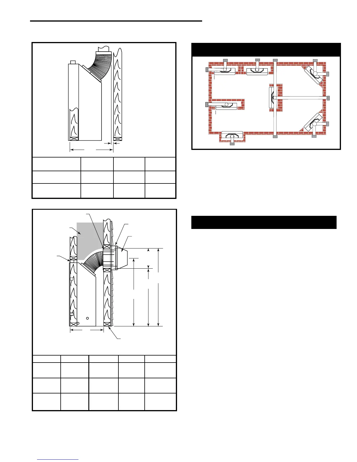
Locating Your Fireplace
Island installation is possible as long as the horizontal
portion of the vent system does not exceed maximum
recommended horizontal run as outlined in the venting chart
on Page 10. When you install your fireplace as in position
'B', 'D' or 'E', (Fig. 1) a minimum of 1” (25mm) clearance
must be maintained from the perpendicular wall and the front
of the appliance.
LU584-1
Fig. 4 Locate gas fireplace.
A) Flat on wall B) Cross Corner C) As an Island
D) As a room divider E) Flat on wall corner F) Exterior wall
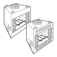
X
1” (25mm) Minimum
Air Space Clearance
to Combustible
Materials
Vent “X”
System Used DV1000MB DV1200MB DV1400MB
TEMCO 4/7 Flex 17¹⁄₂”18¹⁄₂”18¹⁄₂”
(445mm) (470mm) (470mm)
TEMCO 4/7 Rigid 18¹⁄₂”19¹⁄₂”19¹⁄₂”
(470mm) (495mm) (495mm)
Fig. 2 Minimum framing depths with vertical takeoff.
 Loading...