www.temcoline.com
DIGITAL PID CONTROLLER
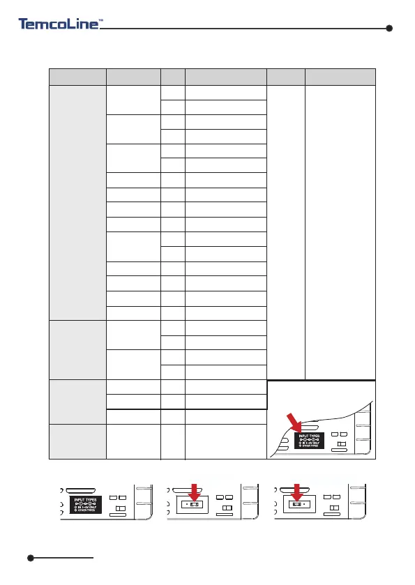
2. Input ranges and Output configuration
1) Input ranges
※ The T30 series has multiple inputs, which may be set and changed by the user.
7
※ How to change the interior switch when using 1~5V input
* F.S is max. value
to min. value of
each range.
* Digit is minimum
of display.
K
J
E
T
R
B
S
L
N
U
C (W5)
D (W3)
JPt100
Ω
(JIS, KS)
Pt100
Ω
(DIN, IEC)
0~100 mV DC
-10~20 mV DC
1~5 V DC
4~20 mA DC
1
2
15
16
3
4
5
6
7
8
17
9
10
12
13
20
22
21
23
33
32
30
30
11
±0.3% of
F.S + 1 Digit
Voltage
(V DC/mV DC)
-200 ~ 1370
-199.9 ~ 999.9
-200 ~ 1000
-199.9 ~ 999.9
-200 ~ 1000
-199.9 ~ 999.9
-199.9 ~ 400.0
0 ~ 1700
400 ~ 1800
0 ~ 1700
-200 ~ 900
-199.9 ~ 900.0
-200 ~ 1300
-199.9 ~ 400.0
0 ~ 2300
0 ~ 2400
-199.9 ~ 500.0
-200 ~ 500
-199.9 ~ 640.0
-200 ~ 640
0 ~ 100 mV DC
-10 ~ 20 mV DC
1~5 V DC
When using current input,
use the resistor 250
on input terminal.
Ω
Input type
Input
Setting
Code
Temperature range
Remarks
Accuracy
Thermocouple
(T.C)
RTD
Current
※ When using 1~5V input
(30), the interior jumper
switch must be relocated.
①
Remove plate or take out
the main cover.
②
Move and insert the
jumper that pulled by
tweezers.
③
Relocated jumper as
above and attach plate
or mounted cover.
MULT-IN MODE
IN 1~5V ONLY MODE