THP-400A, THP-500A and THP-550 Installation and Service Manual
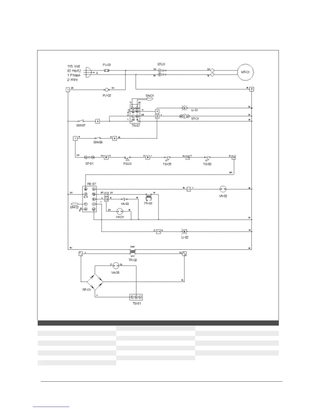
Component Identification
FU-01 main fuse SN-01 low-temperature sensor TS-04 high-temperature limit switch
FU-02 control fuse SN-02 flame rod TS-07 low-temperature limit switch
LI-01 low-temperature light ST-01 motor starter TS-11 room-override thermostat
LI-02 burner-reset light SW-06 burner switch VA-01 main-gas valve
MT-01 supply-blower motor SW-07 blower switch VA-02 2nd main-gas valve
PS-01 air flow switch TR-02 low-voltage transformer VA-03 pilot-gas valve
RE-07 flame-safety relay TR-03 ignition transformer VA-05 modulating gas valve
RF-01 rectifier TS-01 discharge-air sensor
Wiring — THP-400A