THP-400A, THP-500A and THP-550 Installation and Service Manual
Component Identification
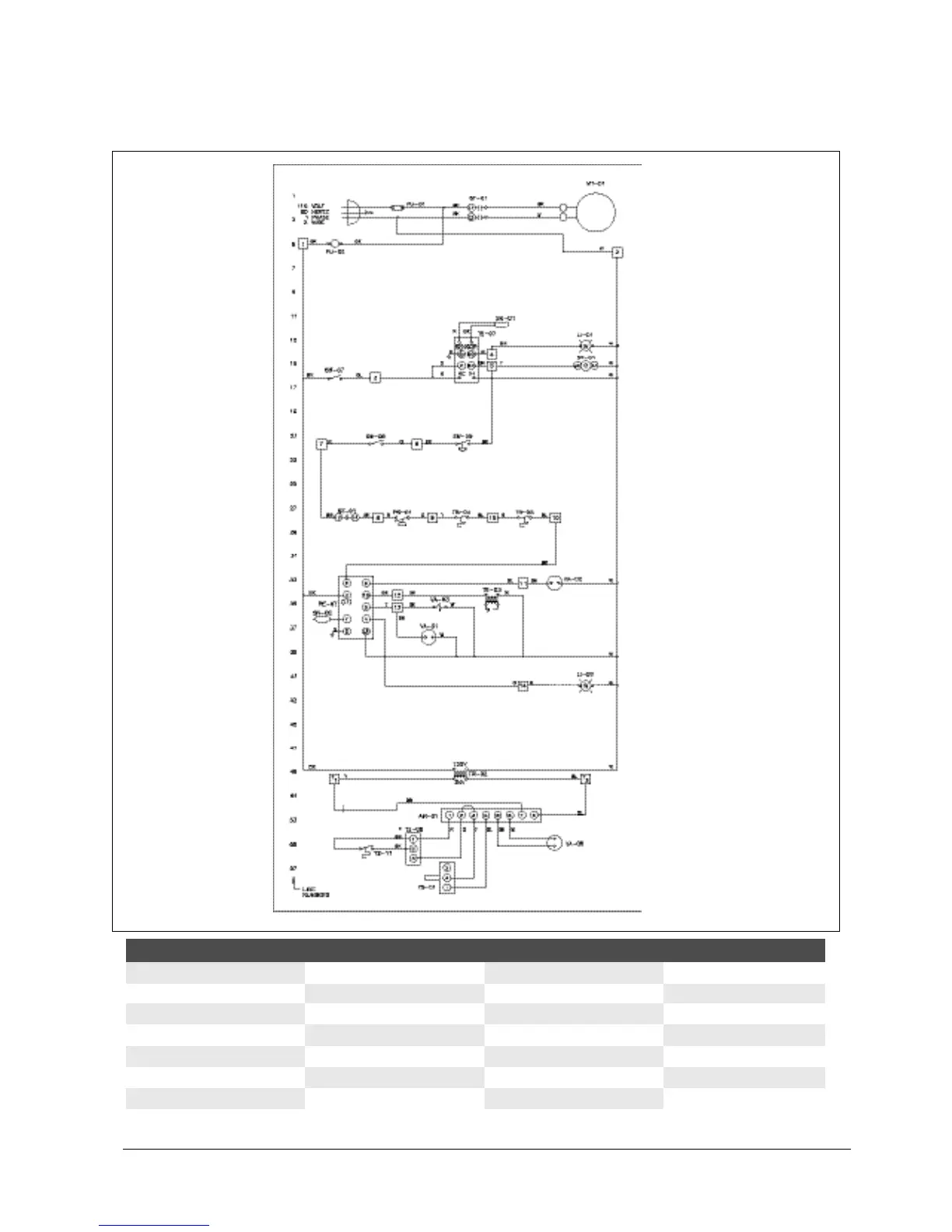
AM-01 amplifier RE-07 flame safeguard relay TR-02 low voltage transformer TS-11 room override thermostat
FU-01 main fuse SN-01 low temp sensor TR-03 ignition transformer VA-01 main gas valve
FU-02 control fuse SN-02 flame rod TS-01 discharge air sensor VA-02 2nd main gas valve
LI-01 "low temp" fuse ST-01 supply fan motor starter (28) TS-04 high temp limit switch VA-03 pilot gas valve
LI-02 "flame" light SW-06 burner service switch TS-05 2nd high temp limit switch VA-04 modulating gas valve
MT-01 supply blower motor SW-07 blower starting switch TS-07 low temp stat/timer
PS-01 low air flow switch SW-09 unit tip over switch TS-08 remote disch. temp. setpoint
Wiring — THP-500A