EasyManua.ls Logo

Tempco TEC-9100 User Manual

Tempco TEC-9100
12 pages
To Next Page IconTo Next Page
Page #1 background imageLoading...
Page #1 background image
Page 1 of 12
TEMPCO Electric Heater Corporation
607 N. Central Avenue
Wood Dale, IL 60191-1452 USA 630.350.2252 Fax: 630.350.0232
E-mail: info@tempco.com
Web: www.tempco.com
Visionary Solutions for Industry
®
Since 1972 ISO 9001 Certified
Temperature Controllers & Sensors Heating Elements Process Heating Systems
®
®
Instructions for TPC Power Through Control Console
SPECIFICATIONS
Temperature Controller: Model TEC-9100, 1/16 DIN Dual Display with PID Auto-tuning
Sensor Input: Type “J” or type “K” thermocouple dependent on model ordered
(Alternative inputs available for special order)
Power Cord/voltage Input: 120VAC or 240VAC (dependent on model ordered)
Heater Output: 8A max for 1-zone consoles
4A max per zone for 2-zone consoles
2.7A max per zone for 3-zone consoles
2A max per zone for 4-zone consoles
Output Device: Solid State Relay
Main Power Switch: Located on front panel
Fuse Main Power: See replacement parts list (located inside power inlet module)
Fuse Control Power: See replacement parts list (located on back panel)
WARNINGS
1. Air vents located on top and bottom of console must not be blocked! To prevent
an overheating condition the internal components must remain as close to room
temperature (75ºF / 24ºC) as possible.
2. Dangerous voltage capable of causing injury or death is present within this console.
Power to all equipment must be disconnected before installation or beginning any
troubleshooting procedures.
Heater output wiring and component replacement
must be made by qualified personnel only.
3. To minimize the possibility of fire or shock, do not expose this console to rain or
excessive moisture.
4. Do not use this console in areas where hazardous conditions exist such as excessive
shock, vibration, dirt, corrosive gases, oil or where explosive gases or vapors are
present.
WIRING (For safety, disconnect all power sources prior to wiring)
1. Attach the leads from your type thermocouple to the mini-plug provided. Take care
to note the correct polarity. The red lead is (-) negative.
2. The heater output current is sourced directly thru the line cord. The rear console
output receptacle and mating Hubbell plug provides live controlled power for direct
connection to your heater(s). Connect one lead from your heater to one prong of
the Hubbell plug (not ground). Connect the other lead from your heater to the other
prong. Connect heater ground (if applicable) to the ground connection (G) on the plug.
© 2015 Tempco Electric Heater Corporation (Revision 4/4/2016)
Question and Answer IconNeed help?

Do you have a question about the Tempco TEC-9100 and is the answer not in the manual?

Tempco TEC-9100 Specifications

General IconGeneral
DisplayDual 4-digit LED
MountingPanel mount
Control ModePID
Input TypeThermocouple, RTD
Output TypeRelay, SSR
Power Supply24 VAC/VDC
Temperature RangeAccording to sensor type
Resolution0.1°C or 0.1°F

Summary

SPECIFICATIONS

Controller and Input Details

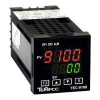
TEC-9100 controller, J/K thermocouple input, 120/240VAC input.

Output and Power Details

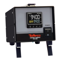
Heater output ratings, Solid State Relay, power switch, and fuse locations.

WARNINGS

Safety Precautions

Covers air vents, electrical hazards, moisture, and hazardous environments.

WIRING

Wiring Instructions

Connect thermocouple and heater outputs, noting polarity and ground.

OPERATION

Initial Setup

Verify power switch, plug in, switch on, and set temperature setpoint.

Controller Operation Reference

Refer to subsequent pages for complete operation and auto-tuning.

SPARE/REPLACEMENT PARTS

Parts Listing

Lists part numbers for fuses, power output plugs, and thermocouple mini-plugs.

Chapter 1 Overview

General Controller Description

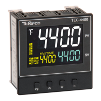
Details TEC-x100 series, displays, Fuzzy Logic, and model variations.

Key Control Features

Highlights high accuracy, fast sampling, fuzzy control, digital comms, and auto-tune.

1–4 Keys and Displays

Keypad Operation

Explains functions of Scroll, Up, Down, Reset, and Enter keys.

Front Panel Description

Details the display layout, indicators, and buttons.

Display During Power Up

Shows program code and version information upon startup.

1–5 Menu Overview

Mode Navigation

Flowchart showing User, Setup, Manual, Auto-tuning, and Calibration modes.

Parameter Access and Selection

Details how to access parameters via User, Setup, and mode menus.

Parameter Notes and Visibility

Explains parameter availability, user menu selection, and hidden parameters.

Parameter Descriptions (TEC-9100 Temperature Controller)

Input and Unit Parameters

Descriptions for Set point, Lock, Input Sensor, Unit, and Decimal Point parameters.

PID and Output Parameters

Descriptions for Proportional Band, Integral Time, Derivative Time, and Output 1 functions.

Filter and Ramp Parameters

Descriptions for Filter damping, Ramp function, and Ramp rate parameters.

Chapter 3 Programming

Lockout Security Levels

Explains the four security levels for preventing parameter changes.

Signal Input Configuration

Details INPT for sensor type, UNIT for process unit, and DP for resolution.

PV Shift

PV Shift Functionality

Explains how to shift the displayed process value (PV) from its actual value.

3-9 Digital Filter

Digital Filter Operation

Describes the programmable low-pass filter for unstable PV signals.

3-10 Failure Transfer

Failure Transfer Operation

Covers conditions, causes, and output behavior during failure mode.

Auto-tuning

Process, Adjustment, and Error Handling

Covers process, PID guide, and ATER messages for auto-tuning.

Manual Tuning

Manual Tuning Application

Guidance for manual PID adjustment when auto-tuning is unsatisfactory.

WARRANTY

Warranty Terms and Limitations

Tempco's warranty for TEC controllers: 2 years, limited to repair/replacement.

RETURNS

Return Merchandise Policy

Requires completed Return Material Authorization (RMA) form.

TECHNICAL SUPPORT

Support Contact Information

Provides contact details for technical questions and troubleshooting.

Related product manuals