SERVICE AND TECHNICAL SUPPORT MANUAL Gas Furnace: (F/G)9MAC
Specifications subject to change without notice.
10 440 04 4201 01
Adjust Thermostat Heat Anticipator
a. Mechanical thermostat. Set thermostat heat
anticipator to match the amp. draw of the electrical
components in the R−W/W1 circuit. Accurate amp.
draw readings can be obtained at the wires normally
connected to thermostat subbase terminals, R and W.
The thermostat anticipator should NOT be in the
circuit while measuring current.
(1.) Set SW1−2 switch on furnace control board to
ON.
(2.) Remove thermostat from subbase or from wall.
(3.) Connect an amp. meter as shown in Figure 5
across the R and W subbase terminals or R and
W wires at wall.
(4.) Record amp. draw across terminals when
furnace is in minimum heat and after blower
starts.
(5.) Set heat anticipator on thermostat per thermostat
instructions and install on subbase or wall.
(6.) Turn SW1−2 switch OFF.
(7.) Install blower door.
b. Electronic thermostat: Set cycle rate for three cycles
per hr.
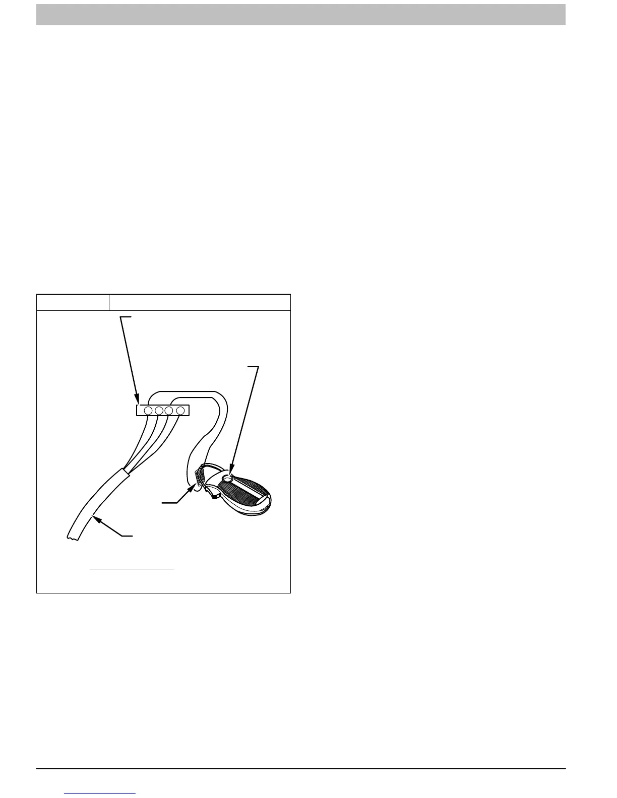
Figure 5 Amp. Draw Check with Ammeter
A96316
R Y W G
10 TURNS
THERMOSTAT SUBBASE
TERMINALS WITH
THERMOSTAT REMOVED
(ANITICIPATOR, CLOCK, ETC.,
MUST BE OUT OF CIRCUIT.)
HOOK−AROUND
AMMETER
EXAMPLE:
5.0 AMPS ON AMMETER
10 TURNS AROUND JAWS
=
FROM UNIT 24−V
CONTROL TERMINALS
Check Safety Controls
The flame sensor, gas valve, and pressure switch were all
checked in the Start−up procedure section as part of normal
operation.
1. Check Main Limit Switch
This control shuts off combustion system and energizes
air−circulating blower motor, if furnace overheats. By
using this method to check limit control, it can be
established that limit is functioning properly and will
operate if there is a restricted return−air supply or motor
failure. If limit control does not function during this test,
cause must be determined and corrected.
a. Run furnace for at least five minutes.
b. Gradually block off return air with a piece of
cardboard or sheet metal until the limit trips.
c. Unblock return air to permit normal circulation.
d. Burners will re−light when furnace cools down.
2. Check Pressure Switch(es)
This control proves operation of the draft inducer blower.
a. Turn off 115−v power to furnace.
b. Disconnect inducer motor lead wires from wire
harness.
c. Turn on 115−v power to furnace.
d. Set thermostat to “call for heat” and wait 1 minute.
When pressure switch is functioning properly, hot
surface igniter should NOT glow and control
diagnostic light flashes a status code 3. If hot surface
igniter glows when inducer motor is disconnected,
shut down furnace immediately.
e. Determine reason pressure switch did not function
properly and correct condition.
f. Turn off 115−v power to furnace.
g. Reconnect inducer motor wires, replace blower door,
and turn on 115−v power.
h. Blower will run for 90 seconds before beginning the
call for heat again.
i. Furnace should ignite normally.
Checklist
1. Put away tools and instruments. Clean up debris.
2. Verify that switches SW1−1 and SW1−6 are OFF and
other setup switches are set as desired. Verify that
switches SW1−7 and SW1−8 for the blower OFF DELAY
are set as desired per Table 2.
3. Verify that blower and control doors are properly
installed.
4. Cycle test furnace with room thermostat.
5. Check operation of accessories per manufacturer’s
instructions.
6. Review Home Owner’s Information with owner.
7. Attach literature packet to furnace.