SERVICE AND TECHNICAL SUPPORT MANUAL Gas Furnace: (F/G)9MAC
Specifications subject to change without notice.
440 04 4201 01 7
FURNACE OVERHEATING HAZARD
Failure to follow this caution may result in shortened
furnace life.
Set air temperature rise within limits specified on the
rating plate to prevent reduced life of furnace
components. Operation is within a few degrees of the
mid−point of rise range when setup switch SW1−4 is
OFF.
CAUTION
!
FURNACE DAMAGE HAZARD
Failure to follow this caution may result in overheating
the heat exchangers or condensing flue gases in heat
exchanger areas not designed for condensate.
Temperature rise must be within limits specified on
unit rating plate. Operation is within a few degrees of
midpoint of rise range when setup switch SW1−4 is
OFF.
CAUTION
!
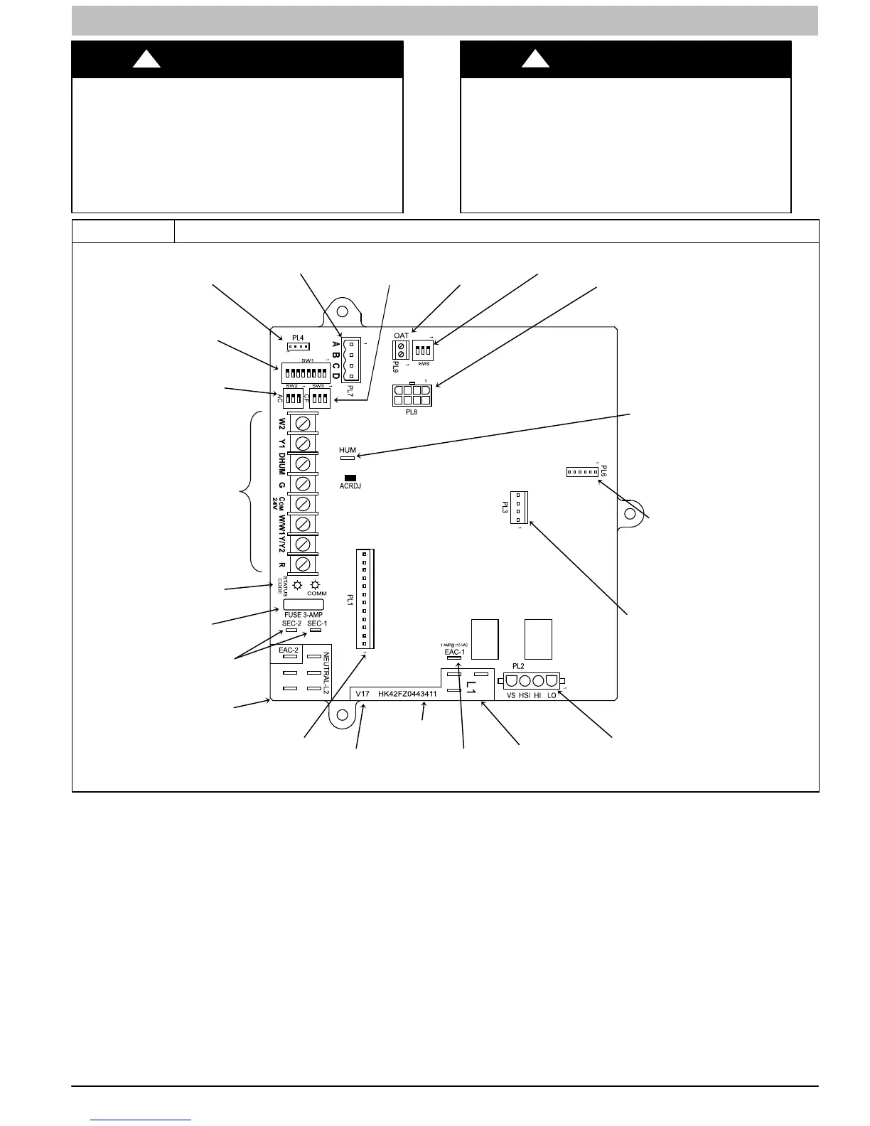
Figure 3 Variable Speed Furnace Control for ECM Blower Motor (Modulating)
TERMINALS
PL2 – HOT SURFACE
IGNITER & INDUCER
MOTOR CONNECTOR
115-VAC (L2) NEUTRAL
CONNECTIONS
115-VAC (L1) LINE
VOLTAGE CONNECTIONS
EAC-1 TERMINAL
(115-VAC 1.0 AMP MAX.)
PL1 – LOW VOLTAGE MAIN
HARNESS CONNECTOR
HARNESS
CONNECTOR
TRANSFORMER 24-VAC
CONNECTIONS
STATUS AND COMM
LED LIGHTS
BLOWER OFF-
AIR CONDITIONING
(A/C) AIRFLOW
SETUP SWITCHES
CONTINUOUS FAN
(CF) AIRFLOW
SETUP SWITCHES
A
-
FLASH
UPGRADE
CONNECTOR
(FACTORY
ONLY)
PART NUMBER AND
DATE CODE WWYY
GAS VALVE
L11F061
Adjust Temperature Rise
When setup switch SW1-4 is ON, operation will be near the
high end of the rise range for improved comfort.
Furnace must operate within ranges of temperature rise
specified on the furnace rating plate. Determine air temperature
rise as follows:
1. Place thermometers in return and supply ducts as near
furnace as possible. Be sure thermometers do not see
heat exchanger so that radiant heat does not affect
readings. This practice is particularly important with
straight-run ducts.
2. When thermometer readings stabilize, subtract return-air
temperature from supply-air temperature to determine air
temperature rise.
NOTE: Temperature rise can be determined for Minimum Heat,
Intermediate Heat and Maximum Heat operation by locking the
furnace in each mode of operation. The mode of operation is
based on the position of Set-up switch SW1-2 and SW4-2 on
the furnace control board.
The furnace is capable of automatically providing proper airflow
to maintain the temperature rise within the range specified on
furnace rating plate. If temperature rise is outside this range,
proceed as follows:
a. Check gas input for Minimum, Intermediate, and
Maximum heat operation.
b. Check derate for altitude if applicable.
c. Check all return and supply ducts for excessive
restrictions causing static pressure greater than 0.5-in.
w.c.
d. Ensure Min/Int Heat Rise Adjust switch SW1−3 on
furnace control is in ON position when a bypass
humidifier is used. (See Figure 3 for switch location.)
e. Check Troubleshooting Guide for Variable−Speed Step
Modulating Condensing Furnaces.