EasyManua.ls Logo

Ten-Tec 555 - User Manual

Ten-Tec 555
59 pages
Print Icon
To Next Page IconTo Next Page
Loading...
This obsolete manual file is provided as a courtesy to you by Ten-Tec, Inc.
Ten-Tec's service department can repair and service virtually everything we have built going
back to our first transceivers in the late 1960's. It is our ability to continue offering service on
these rigs that has led to their re-sale value remaining high and has made a major contribution to
our legendary service reputation.
Printed and bound copies of all manuals are available for purchase through our service
department if you would prefer not to use this copy as your transceiver manual.
We can repair or service your Ten-Tec equipment at our facility in Sevierville, TN. We also offer
support via telephone for all products via during usual business hours of 8 a.m. to 5 p.m. USA
Eastern time, Monday through Friday. We have a large supply of parts for obsolete products.
Repairing a transceiver or amplifier yourself? Contact us for parts pricing information.
Service department direct line: (865) 428-0364
Ten-Tec office line: (865) 453-7172
Service department email: service@tentec.com
Address: 1185 Dolly Parton Parkway, Sevierville, TN 37862 USA
We have found it is most effective for us to help you troubleshoot or repair equipment with a
consultation via telephone rather than by email.
Suggested contact methods are:
Troubleshooting or repairing equipment – call (865) 428-0364
Other inquiries – call (865) 428-0364 or email service@tentec.com
THANK YOU AND 73 FROM ALL OF US AT TEN-TEC
Question and Answer IconNeed help?

Do you have a question about the Ten-Tec 555 and is the answer not in the manual?

Summary

Model 555;556 Specifications

General Specifications

Covers general specifications including modes, frequency range, display, and construction.

Transmitter Specifications

Details transmitter specifications like RF output, DC input, microphone input, and CW offset.

Receiver Specifications

Details receiver specifications like sensitivity, selectivity, dynamic range, and noise floor.

Introduction to SCOUT;ARGO

Unpacking Your Transceiver

Instructions and precautions for unpacking the SCOUT/ARGO transceiver and its accessories.

Chapter 1: Installation

Power Supply Requirements

Details power supply requirements, connections, and fuse protection for the transceiver.

Antenna Connection

Guidance on connecting antennas, impedance, and SWR considerations for optimal operation.

Microphone Connection

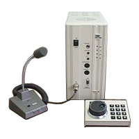
Information on compatible microphones and their connection to the transceiver.

CW Key and Keyer Operation

Details on connecting external CW keys and using the built-in iambic keyer.

Station Grounding

Importance of proper grounding for optimum operation and RFI prevention.

Ten-Tec Accessories

List of available Ten-Tec accessories for the SCOUT/ARGO models.

Commercial Connectors and Adaptors

Helpful connectors and adaptors available from local stores for accessory connection.

Installing the Noise Blanker

Step-by-step instructions for installing the optional noise blanker model 297.

Chapter 2: Operating Instructions

Initial Control Settings

Guide to setting initial controls for basic transceiver operation.

Main Tuning and PTO

Explanation of the main tuning knob, PTO, and FLS frequency lock system.

Frequency Readout and Display

How to interpret the LED display for frequency and understanding band edge behavior.

Band Module Selection

Instructions for inserting and selecting band modules for different amateur bands.

Using the Front Panel Meter

Explanation of the meter scales for S-meter, forward power, and SWR.

Getting on the Air

Steps to connect an antenna, check SWR, and prepare for transmitting.

SSB Operation Guide

How to operate the transceiver in Single Sideband (SSB) mode.

CW Operation Guide

Instructions for CW operation, including keyer use and sidetone adjustment.

Transmit Power Output Adjustment

Details on transmit power output for SCOUT and ARGO models and adjustments.

Front Panel Controls Explained

Detailed explanation of each front panel control and its function.

Chapter 3: Circuit Descriptions and Illustrations

Receiver Control Board (81644)

Description and alignment of the receiver control board circuit.

I.F. Audio Board (81646)

Description and alignment of the IF audio board and its components.

LLD;ALC Board (81707;81725)

Description and alignment of the LLD/ALC board for transmit signal and ALC.

50 W PA Board (81643)

Description and alignment of the 50W Power Amplifier board.

PTO Board (81647)

Description of the PTO board for frequency control and tuning.

Band Modules (81679-81687)

Explanation of band modules for selecting amateur bands and their function.

LED Display Board (81651)

Description of the LED display board and its integrated circuitry.

Frequency Counter Logic Board (81650)

Description of the frequency counter, keyer, and display control logic board.

Noise Blanker (81697)

Description of the noise blanker circuit for reducing pulse noise.

Main Wiring Diagram

Main Wiring Diagram for Model 556

Visual representation of internal wiring connections for the Model 556 transceiver.

Limited Warranty and Service Policy

Ten-Tec 555 Specifications

General IconGeneral
Selectivity2.4 kHz at -6 dB
TypeTransceiver
ModesCW
Power Output5 W
Receiver Sensitivity0.5 uV

Related product manuals