Do you have a question about the Ten-Tec Orion 565 and is the answer not in the manual?
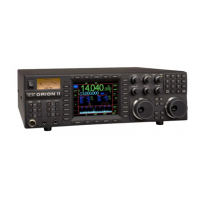
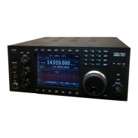
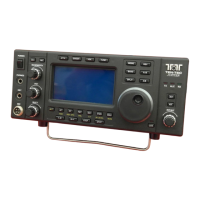
Introduces the ORION as a significant advancement in HF transceiver technology for amateur radio use.
Provides instructions on inspecting the transceiver for shipping damage and retaining packaging for future use.
Specifies power supply requirements, including voltage, amperage, and recommended wire gauge for safe operation.
Emphasizes the necessity of proper grounding for optimal transmitter performance and safety.
Details ORION's unique features, such as mode-appropriate roofing filters and DSP bandwidth filtering, for superior receiver performance.
Describes the front panel analog meter's function for displaying signal strength and output power.
Explains the function of the POWER button to turn the transceiver on and off.
Details how antenna selection keys assign antennas to main and subreceivers for flexible operation.
Explains assigning VFOs to receivers and transmitter, offering flexible dual receive capabilities.
Covers microphone connection, pinout, and compatibility for optimal audio input.
Warns against mono plugs and details using stereo headphones for full audio feature access.
Describes CW keying jacks and enabling the internal keyer for Morse code operation.
Explains the PWR button for setting RF output power and its role in amplifier tuning.
Details the monitor function for listening to transmitted audio and adjusting its level.
Describes the SP control for speech processing in SSB and CW keyer speed adjustment.
Covers CW and voice memories for sending recorded messages or CW sequences.
Explains user profiles for saving and recalling radio configurations, offering advanced memory management.
Details how to recall memories, factory defaults, or user profiles using the RECALL button.
Describes the DSP noise blanker for reducing receiver noise, adjustable for each receiver.
Explains DSP noise reduction for improving signal-to-noise ratio, with adjustable settings.
Details the manual notch filter for rejecting interfering carriers by adjusting center frequency and width.
Explains how to select different operating modes for the transceiver.
Describes the adjustable tuning step size for each receiver, offering seven increments.
Details the five selectable AGC settings for automatic gain control, adjustable per receiver.
Explains accessing and navigating the transceiver's menu system for advanced settings.
Covers audio routing and mixing options for main/sub receivers to speakers or headphones.
Details the PBT/BW encoder for adjusting receiver bandwidth and passband tuning.
Explains the HI CUT/LO CUT control for modifying filter passband edges.
Describes the RIT/XIT encoder for adjusting receiver/transmit incremental tuning.
Identifies the primary tuning knob for VFO A operation.
Explains control of receiver functions and independent setting adjustments.
Details the keypad for direct frequency entry and band selection.
Configures transmitter settings, including internal tuner, transmitter disable, and keying loop options.
Adjusts CW specific settings like QSK delay, keyer weighting, sidetone, and rise/fall times.
Manages VOX operation settings, including gain, anti-VOX, and hang time for voice transmit.
Configures receiver settings such as sweep range, AGC parameters, squelch, and PBT/BW step size.
Contains miscellaneous settings for remote pod controls, VFO behaviour, and display options.
Adjusts SSB transmit parameters like bandwidth, LF rolloff, and audio input source.
Allows selection and adjustment of IF roofing filters and DSP bandwidth filters for optimal reception.
Covers fundamental transceive operation, VFO assignment, and basic audio/antenna setup.
Explains setting up split frequency operation for listening and transmitting on different frequencies simultaneously.
Details enabling and using the internal antenna tuner for impedance matching.
Guides on connecting linear amplifiers, covering keying, PTT, and delay settings.
Discusses controls impacting SSB transmit audio quality, including mic, EQ, and bandwidth.
Explains AM transmit setup, including bandwidth doubling and carrier amplitude control.
Covers FSK operation for RTTY, including rear panel connections and tone selection.
Describes connecting a VHF/UHF transverter using rear panel jacks and TX menu activation.
Explains using dual receivers for diversity reception to improve weak signal copy.
Provides optimal settings for weak signal DXing and contest operation, leveraging Orion's capabilities.
Details using external CW sources with the Orion's internal keyer via AUX I/O.
Describes how to adjust the drag on the main tuning knobs for preferred tactile feedback.
Outlines the procedure for performing a master reset to restore factory defaults or clear user settings.
Explains how to upgrade transceiver firmware via the internet using a computer.
Offers guidance on resolving common operational issues with the transceiver.
Presents general specifications of the ORION transceiver, including frequency range, modes, and display details.
Lists the 13 main printed circuit board subassemblies and one optional subassembly.
Maps the physical placement of subassemblies within the ORION transceiver chassis.
Traces the RF signal path for the main receiver from antenna input through processing to audio output.
Details the RF signal path for the subreceiver from antenna input through processing to audio output.
Outlines the signal path for the transmitter, from audio sources to the RF output.
| Type | HF Transceiver |
|---|---|
| Frequency Range | 1.8 - 30 MHz |
| Power Output | 100 W |
| Receiver Type | Superheterodyne |
| IF Rejection | > 80 dB |
| Image Rejection | > 80 dB |
| Spurious Rejection | > 80 dB |
| Supply Voltage | 13.8 VDC |
| Modes | SSB, CW, AM, FM |
| IF Bandwidths | 2.4 kHz, 500 Hz |
| Audio Output | 2.5 W at 8 Ohms |