Do you have a question about the Ten-Tec ORION II and is the answer not in the manual?
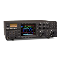
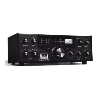
Highlights Ten-Tec's advancements and design goals for the Orion II transceiver.
Instructions for checking the transceiver for shipping damage and retaining packaging.
Provides context on the manual's version and firmware update information.
Details requirements for a stable DC power source and proper connection procedures.
Explains the importance of a good ground system for transmitter operation.
Compares Orion II's advanced features, particularly its roofing filters, to competitors.
Discusses factors affecting frequency stability, including local oscillators and TCXO.
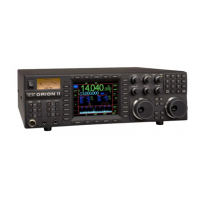
Describes the front panel analog meter and its S-unit display for receive.
Explains the function of the power button to turn the transceiver on and off.
Details how to assign antennas to main and subreceivers using front panel buttons.
Explains how to assign VFOs to receivers and transmitter for flexible operation.
Describes the 8-pin microphone jack and recommended wiring for optimal audio.
Details the front panel headphone jack for stereo or mono headphone use.
Explains the CW key jacks and how to enable the internal keyer for Morse code.
Describes the PWR button and MULTI knob for adjusting RF power output.
Explains the MON button for monitoring transmitted audio and FSK tones.
Details the SP button's function for speech processing in SSB and keyer speed in CW.
Describes the voice and CW memory recording and playback capabilities.
Explains how to save and recall radio settings using USER 1 and USER 2 profiles.
Details how to recall factory defaults, user profiles, and stored memories.
Describes the adjustable DSP noise blanker for suppressing receiver noise.
Explains the DSP noise reduction feature adjustable for each receiver.
Details the manual notch filter for IF level interference removal.
Describes the AN button for automatic notching of carriers in voice modes.
Explains how to select various operating modes like USB, LSB, CW, AM, FM, FSK.
Details the 12 dB gain preamp for the main receiver's front-end.
Explains RF GAIN for limiting receiver sensitivity and adjusting for signal conditions.
Describes the SPOT button for CW sidetone and zero-beat tuning assistance.
Details the STEP button for adjusting tuning step sizes for each receiver.
Explains the SWEEP button for activating the real-time band sweep display.
Describes the five selectable AGC settings and their independent adjustment.
Details the ATTN button for selecting receive attenuation levels.
Explains how to access and navigate the transceiver's various menu systems.
Describes the AUDIO menu for mixing and routing audio to speakers/headphones.
Explains how to enable and adjust VOX (Voice Operated Transmit) settings.
Details the S-TONE button for adjusting CW sidetone volume.
Describes how to set DSP microphone gain for optimal SSB transmit audio.
Explains the TUNE button for antenna tuner activation and amplifier tune-up.
Describes the ALC light function for indicating automatic level control.
Explains the bargraph meter display for subreceiver signal strength reference.
Details the PBT/BW encoder for adjusting receiver bandwidth and passband tuning.
Explains the MULTI encoder's role in controlling various transceiver values.
Describes the HI CUT and LO CUT controls for modifying receiver passband edges.
Details the MAIN AF encoder for adjusting main receiver volume.
Details the SUB AF encoder for adjusting sub receiver volume.
Explains the RIT/XIT encoder for setting receive/transmit incremental tuning.
Identifies the left main tuning knob for VFO A operation.
Details the RIT button for turning Receive Incremental Tuning on/off.
Explains how to store frequencies from VFO A/B into the memory system.
Describes the LCK buttons for locking the main tuning knobs for VFO A/B.
Details the XIT button for turning Transmit Incremental Tuning on/off.
Identifies the right main tuning knob for VFO B operation.
Explains how SUB RX and MAIN RX buttons control receiver command assignment.
Details the keypad for direct frequency entry and band selection.
Describes how to enter frequencies directly into VFO A using the keypad.
Describes how to enter frequencies directly into VFO B using the keypad.
Explains the A>B, B>A, A/B buttons for copying or flipping VFO frequencies.
Details the ANT 1 connector for transceive antenna connection.
Details the ANT 2 connector for a second transceive antenna connection.
Specifies the DC input requirements and recommended power cable usage.
Provides details on the 25-ampere blade-type automotive fuse and replacement.
Explains the GND wingnut for station ground or counterpoise connection.
Details AMP KEY 1 for connecting non-QSK linear amplifiers.
Explains TX OUT/TX EN 1 for full break-in keying loops with linear amplifiers.
Details AMP KEY 2 for connecting a second linear amplifier.
Explains TX OUT/TX EN 2 for full break-in keying loops with a second amplifier.
Describes the +13.8 VDC jack for connecting accessory equipment.
Details the RCA-style connector for connecting a receive-only antenna.
Explains XVRT KEY and XVTR RF for connecting external transverters.
Details the line level audio output for main, sub, or both receiver audio.
Identifies the SPARE jack for future use or custom modifications.
Describes BAND DATA 1 and 2 for switching accessory devices via band selection.
Details the EXT SPKR jack for connecting an external speaker.
Explains the rear panel CW key jack, parallel to the front panel jack.
Details the 8-pin DIN AUX I/O jack for audio, FSK, and PTT interface.
Describes the REMOTE jack for connecting the model 302R accessory.
Explains the serial data connector for firmware updates and computer control.
Configuration options for the transmitter, including tuner and keying loop settings.
Settings for CW operation, including QSK delay, weighting, and sidetone pitch.
Adjustments for Voice Operated Transmit (VOX) trip level, anti-VOX, and hang time.
Settings for receiver functions, including sweep range, AGC, and noise reduction.
Miscellaneous settings for remote pod functions, LCD display, and data inputs.
Configuration options for SSB operation, including audio gain and TX bandwidth.
Settings for selecting and enabling optional crystal roofing filters and DSP filters.
Guides on setting up VFOs for typical transceive operation with main and subreceivers.
Instructions on how to use dual receivers for split frequency operation with DX stations.
Explains how to enable, use, and tune the optional internal automatic antenna tuner.
Details methods for connecting linear amplifiers, including QSK and non-QSK setups.
Provides steps for initial tune-up of an external linear amplifier using the TUNE button.
Guides on adjusting factors affecting SSB transmit audio quality for optimal sound.
Explains how to configure settings for AM transmit operation, including PWR and EQ.
Details how to set up and operate the transceiver in FSK (RTTY) mode.
Provides guidance on connecting VHF/UHF transverters to the transceiver's rear panel.
Explains how to use dual receivers and antennas for diversity reception benefits.
Offers advanced settings and strategies for optimizing performance in weak signal and contest environments.
Instructions on how to adjust the drag force of the main tuning knobs.
Guides on the physical installation of optional crystal roofing filters.
Details the steps to perform a master reset for restoring factory settings.
Explains how to download and install firmware updates via the internet.
Addresses common problems like no audio, distorted transmit, and no transmit.
Covers frequency range, modes, supply voltage, and operating temperature.
Details SSB sensitivity, IMD3 dynamic range, and IF selectivity for the main receiver.
Details SSB sensitivity and selectivity for the secondary receiver.
Details power output, TX bandwidth, and microphone input characteristics.
Details internal components, subassembly layout, and signal paths within the transceiver.
Describes the physical placement of internal circuit boards and modules.
Traces the RF signal flow from antenna to audio for the main receiver.
Traces the RF signal flow from antenna to audio for the subreceiver.
Traces the signal path from audio input to RF output for transmission.
| Type | HF Transceiver |
|---|---|
| Frequency Range | 1.8 - 30 MHz |
| Modes | SSB, CW, AM, FM, Digital |
| Power Output | 100 W |
| IF Rejection | > 80 dB |
| Image Rejection | > 80 dB |
| IF Frequencies | 9 MHz, 455 kHz |
| Display | LCD |
| Power Supply | 13.8 V DC |
| IF Bandwidths | 2.4 kHz, 500 Hz |
| Audio Output | 2.5 W |