12Revision 1.1 08/18/2005
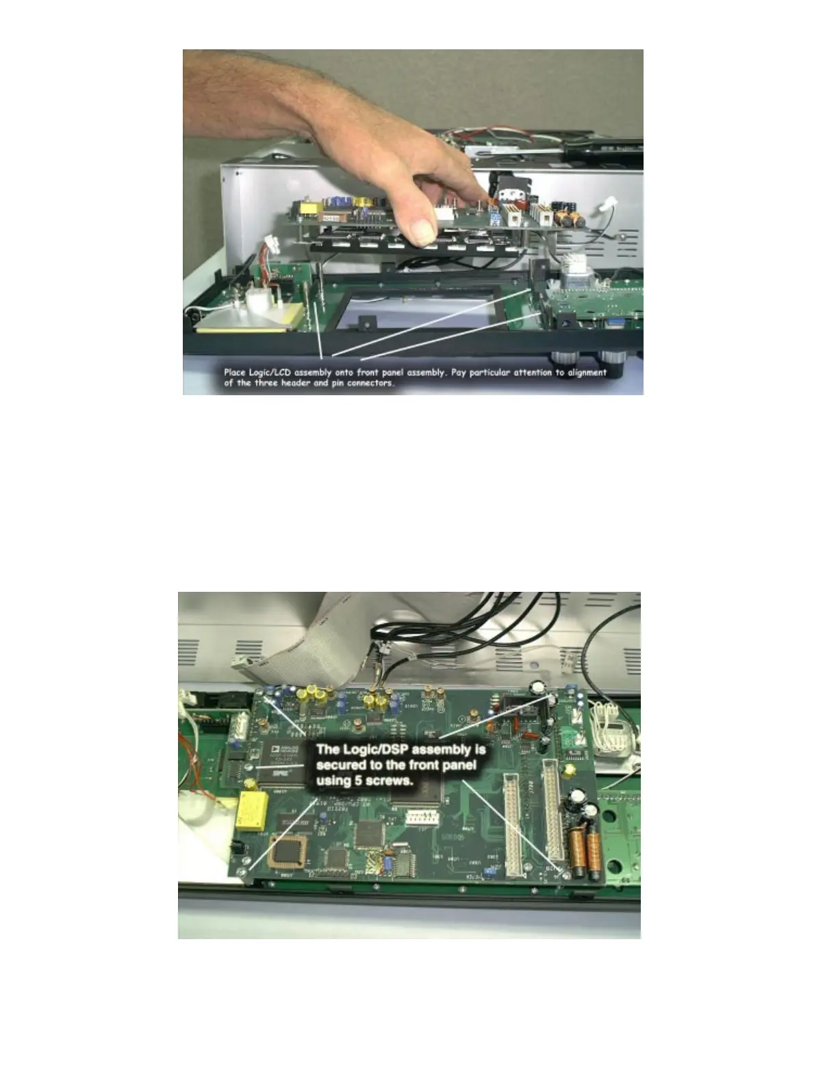
Step 13: Attach the Logic/DSP/LCD assembly to the front panel.
There are 3 multi-pin connectors that must be mated during this step.
After assembly, inspect the connectors closely to insure they are
properly aligned and there are not bent pins.
Step 14: Secure the Logic/LCD assembly to the front panel using 5
screws placed at locations shown.