01
Get to know your device
Power on the CPE
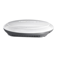
LED indicators (Figures 1-2)
The following table lists all LED indicators that are used on the
CPE. However, the LED indicators may vary with CPE models.
Ports, buttons and slots (Figures 3-5)
The following table lists all ports, buttons and slots that are used
on the CPE. However, the ports, buttons and slots may vary with
CPE models.
Connect the PoE injector to the CPE as guided in Connect
the CPE.
Get to know the PoE injector (Figure 6)
Option 1: Use the PoE injector
DescriptionStatusLED indicator
Power
Solid on CPE powered on
Off CPE powered off
Solid on
Blinking
Off
Off
The CPE is powered off.
Solid on
Blinking
Off The port is disconnected.
PoE/LAN
PoE/LAN1, LAN2,
LAN3, LAN4
Solid on/
Blinking
LED1, LED2, LED3
CPE bridged or connected to
other devices.
Solid on: CPE working in AP or
Router mode.
Blinking: CPE working in Client,
Universal Repeater or WISP mode.
The more indicators are on, the
better the connection quality is.
No device is connected to the CPE
wirelessly, or the signal strength is
weak. Adjust your CPE's direction or
location.
You can change the signal strength
values for each indicator in the web
UI of the CPE.
The quantity of LED indicators and
available working modes vary with
CPE models.
Tips
−
−
(Received signal
strength indicator)
The CPE is powered on. No data is
transmitted.
The port is connected. Data is
being transmitted.
The port is connected. No data is
transmitted.
The CPE is powered on. Data is
being transmitted.
−
−
DescriptionPort/Button/Slot
PoE/LAN,
PoE/LAN1
LAN2, LAN3,
LAN4
RESET, Reset
Cable grommet
Reset button. Used to restore the CPE to factory
settings.
Reset method: Use a paper clip to press the reset
button on the device for 8 seconds.
Used to fix the power cord or Ethernet cable.
Wall mounting
slots
Used to fix the CPE to a wall. Recommended
specifications for expansion bolts and screws:
Expansion bolt: height: 6.6 mm, inner
diameter: 2.4 mm, length: 26.4 mm
Screw: thread diameter: 3 mm, length: 14 mm,
head diameter: 5.2 mm
Pole mounting
slots
Used to fix the CPE to a pole using the included
plastic straps.
Ethernet port for connecting to a computer, switch
or IP camera.
Multiplexing port for PoE power input and data
transmission.
If passive PoE is used for power supply, connect
this port to the PoE port of the PoE injector.
If you power on the CPE using a power adapter,
this port can be connected to a computer,
switch or IP camera.
DC power jack.
Connect the power adapter (if any) to this port for
power supply.
12V 1A, DC
Tips
If the CPE works in the Router mode (if supported), this
port functions as a WAN port to connect an upstream
network device.
−
−
−
−
Port Description
DC Power jack.
PoE
LAN
PoE power output port.
Use an Ethernet cable to connect this port to the passive PoE
port of the CPE.
LAN port.
Used to connect network devices such as a computer,
switch, or camera.
Connect the CPE
You can see the working mode of the CPE on its label. In the
following figures, the CPE is powered on by the PoE injector.
Application scenarios
Install the CPE labelled with NVR Side at the NVR side and the
CPE labelled with Camera Side at the camera side.
The following demonstrates how pole mounting enables
monitoring in different scenarios. When using this method, route
the plastic straps through slots at the back of the CPEs, and
properly position the CPEs on the poles before tightening the
straps.
After successful installation, the bridging quality reaches the best
when the CPEs' received signal strength indicators (such as
LED1, LED2 and LED3) are all solid on or blinking.
Log into the CPE
The following procedure describes how to log into the web UI of
the CPE on a computer.
Connect the computer to the LAN port of the CPE or the LAN
port of the switch connected to the CPE.
Set the computer's IP address to the same network segment
as the CPE's IP address. For example, if the CPE's IP address
is 192.168.2.1, then the computer's IP address can be set to
192.168.2. ( ranges from 2 to 254 and is unused), and the
subnet mask is 255.255.255.0.
Start a web browser on the computer connected to the CPE
and enter the default CPE's IP address (192.168.2.1 in AP
mode or 192.168.2.2 in Station mode) in the address bar. Enter
the username and password and click Login.
Scenario 1: The machine room located close to the top of the
elevator shaft (Figure 11)
Scenario 2: The machine room located close to the bottom of
the elevator shaft (Figure 12)
Connect the CPE labelled with NVR Side to the switch that
connects to the NVR.
Connect the NVR side-CPE to the NVR
(Figure 7)
Construction tower crane (Figure 9)
Community, factory and farm (Figure 10)
Elevator
CAT5 Ethernet cables or above are recommended for higher speed.
Tips
If the CPE has a DC power jack, use the included power
adapter to power on the CPE.
Option 2: Use the power adapter
Use the included power adapter to avoid damage to the CPE.
Tips
The two CPEs are pre-configured and ready for installation.
Tips
Connect the CPE labelled with Camera Side to the switch
that connects to the IP camera.
Connect the Camera side-CPE to the IP
camera (Figure 8)
1.
2.
3.
You can also log into the web UI of the CPE using its WiFi. By default, the CPE WiFi
name is Tenda_ or Tenda__MG ( indicates the last six
characters of the CPE MAC address). If you cannot find the WiFi network, try
restarting the CPE.
To ensure network security, change your username and password after first login.
Tips
-
-
 Loading...