Do you have a question about the Tenma 72-10500 and is the answer not in the manual?
General safety precautions for operating the device.
Information on AC input voltage and grounding requirements.
Important notes regarding fuse replacement for fire protection.
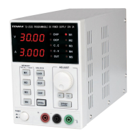
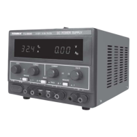
Overview of the front panel controls and their functions.
Description of the voltage and current displays and status indicators.
Instructions for operating the power supply in series mode.
Instructions for operating the power supply in parallel mode.
Procedure for setting output voltage and current levels.
Troubleshooting when panel buttons are unresponsive due to lock.
Diagnosing no output when current setup is zero.
Understanding why output shuts off when OCP or OVP is active.
Explaining the logic behind OCP/OVP LED indication.
Detailed specifications for models 72-10500, 72-10505, and 72-10495.
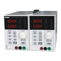
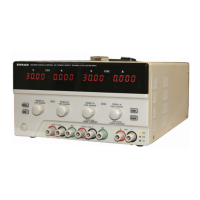
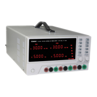
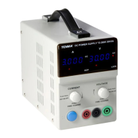
The TENMA 72-10495, 72-10500, and 72-10505 are digital-control DC power supplies designed for various applications. The 72-10495 model offers two channels with 30V-5A output, while the 72-10500 and 72-10505 models provide two channels with 30V-3A output. The 72-10505 also includes an additional 5V-3A channel. These devices are characterized by their low noise, compact size, and light weight, making them suitable for indoor use in dust-free, non-conductive environments.
The power supplies operate in both constant voltage (CV) and constant current (CC) modes, automatically switching between them as needed. They feature digital panel control for setting output parameters, including voltage and current. Each channel has a 4-digit display for both voltage and current, offering a resolution of 10mV/1mA. The devices support output On/Off control and include a beep output for audible feedback.
| Brand | Tenma |
|---|---|
| Model | 72-10500 |
| Category | Power Supply |
| Language | English |